4
\$\begingroup\$

Note: the key question is now in bold at the bottom, for the people who have had trouble figuring out what I'm trying to ask. Sorry about the meandering explanation.

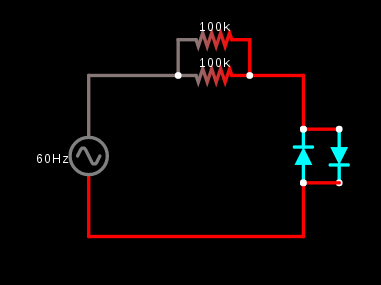
I've been experimenting with resistive droppers lately, and designed the following very simple circuit:

Resistive dropper circuit

To clarify, this is not just theory. I did this in the real world. The simulator screenshot is just to show how the circuit is arranged.

The input is 120v AC, 60Hz. I used two generic high brightness white LEDs (rated for 30mA, 3v). I didn't do any rigorous calculations, and just made ballpark estimates. And yet, somehow, when I measured it, there is exactly 3v across the LEDs. How on earth does this work so well? Are the LEDs somehow self-regulating their resistance so that there's as close to 3v across their terminals as they can get? Or was I just somehow really lucky?

I later measured the current traveling thru the circuit, and it's around 2.4mA, which is exactly what you'd predict according to ohm's law (120 v / 50000ohm = 0.0024A = 2.4mA). (All measurements were done with a okayish digital multimeter. I don't have an oscilloscope, sadly.) I've tried running thru what I know, and so far have figured out that the LED does not have a linear resistance curve, which is, of course, no surprise. At 30mA and 3v, it has 100 ohms of resistance. But when I try to use that figure to predict how much voltage drop to expect, I end up with around .23v. I've tried looking up the electrical characteristics of my generic-y LEDs, but the distributor didn't give a part number, let alone a datasheet.

(I later actually tested the current draw at 3v, and it was actually 15mA, which gave me a nominal resistance of 200 ohms (3v / .015A = 200ohm). Which didn't help matters -- that just predicts a current of 0.47v. I've also tried plugging everything in at once without rounding, which unsurprisingly doesn't help either.)

I thought maybe there was some sort of AC black magic here that somehow involved the minimum forward voltage of the LED, but I tested it and it's around 2.5 volts... besides, I see nowhere for voltage to build up.

So... is this normal? Are the LEDs somehow "self regulating" their resistance so as to get 3v across their terminals?

\$\endgroup\$
11
  • 1
    \$\begingroup\$ Did you actually connect this physically, or are you asking about the properties of the simulator? \$\endgroup\$
    – pipe
    Commented Nov 23, 2017 at 22:23
  • 1
    \$\begingroup\$ Yes, this is how diodes work. The voltage across a diode (when it's turned on) is roughly constant. (It's not really, but it's a lot more constant than, say, the voltage across a resistor) \$\endgroup\$ Commented Nov 24, 2017 at 1:49
  • 1
    \$\begingroup\$ Ya but unfortunately measuring AC across a diode wont give you a true reading. \$\endgroup\$
    – Trevor_G
    Commented Nov 24, 2017 at 2:09
  • 2
    \$\begingroup\$ Did you plug this circuit directly into mains? Please don't. \$\endgroup\$
    – Mast
    Commented Nov 24, 2017 at 8:09
  • 2
    \$\begingroup\$ A GFCI isn't going to do anything in this case, so you probably do need that lecture. That 10A fuse will prevent the most obvious fire hazards, but won't keep you safe from electrical ones. It's your life, sure, but you really don't know what you're playing with. Don't claim you do. \$\endgroup\$
    – Mast
    Commented Nov 24, 2017 at 14:11

7 Answers 7

3
\$\begingroup\$

The answer to your question is "Yes", at least to some extent. An LED is a diode, and semiconductors have nonlinear behavior. Those are fancy words meaning, "not like a resistor". In particular, the fact that they don't conduct (significant) current until they reach a certain voltage is mostly what you've found. Silicon diodes will have around .6 to .7 volts across them when conducting; so will a transistor's base-emitter junction. Germanium does the same thing at around .3 volts. Zener diodes have this behavior at some rated reverse voltage. LED's do this at around 3 volts (depends on color because of materials and doping).

After the diode junction is conducting, if you try to raise the voltage, the diode will try to conduct more current. That's because once it's conducting, it acts as if it has a fairly low series resistance. In fact, a simple model of a diode is a voltage source in series with a small resistance. If, in your circuit, there is any other significant resistance (your 100k is way more than enough), then the increased voltage appears across that resistance, and the diode just draws more current.

I have seen a red LED used as a voltage regulator. I wasn't a particularly good regulator, but it was enough to do the job in that application.

\$\endgroup\$
7
\$\begingroup\$

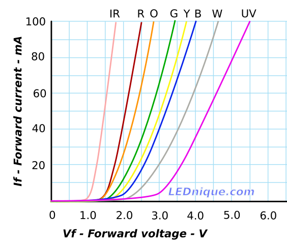
LEDs forward voltage and current are described in the I/V curve:

enter image description here

By limiting the current with the 50kOhm equivalent resistance, you probably put the LED in the region with about 3V of forward voltage (if that is what you measured).

In reality the calculation would be:

120Vrms - 3V = 50000R * i

i = 117/50000 = 0.00234A = 2.34mA

p.s.: IRL don't use a single resistor in series with 120V AC, they aren't normally rated to withstand 200V peak. Use multiple in series. Or don't experiment with 120V AC at all if you are a beginner.

p.p.s.: differences measured IRL can be explained by resistor, LED and AC socket voltage tolerances. (from comments: Also, you'll be measuring rectified AC. Many multimeters don't deal well with that since they do an approximate calculation for RMS values considering a sine wave.)

\$\endgroup\$
9
  • \$\begingroup\$ Yes, I realize that the LED is dropping some voltage, and thus the theoretical current should be a tiny bit lower... but that's not really what I'm asking here. I'm confused as to why the voltage across the LEDs is so conveniently at exactly 3v. Your VI curve shows that it should be at 20mA to have 3v. I expected to see something like 2v across the LEDs. \$\endgroup\$
    – ad555
    Commented Nov 23, 2017 at 22:29
  • \$\begingroup\$ I used a random I/V curve from the internet to describe them in general. Ideally, you would have the one for your LED. Vf tend to be similar for similar colors though. \$\endgroup\$
    – Wesley Lee
    Commented Nov 23, 2017 at 22:32
  • \$\begingroup\$ Fair enough. :P Sadly, as I said, I don't have the curve. \$\endgroup\$
    – ad555
    Commented Nov 23, 2017 at 22:34
  • \$\begingroup\$ Also, you'll be measuring rectified AC. Many multimeters don't deal well with that since they do an approximate calculation for RMS values considering a sine wave. Honestly though, try to not experiment with electronics on a power socket. It is quite dangerous. As I said, most resistors aren't rated to sustain that. \$\endgroup\$
    – Wesley Lee
    Commented Nov 23, 2017 at 22:35
  • \$\begingroup\$ I know what I'm doing, more or less. With dry hands, at 120v, and a GFCI, and a homemade fuse box (in addition to the house breakers), I think I'm pretty safe from current surges causing an explosion. But if it was 240v I wouldn't touch it. :P But for anyone who doesn't know about parasitic capacitance effects or doesn't understand V = IR, I definitely wouldn't recommend they mess with it. \$\endgroup\$
    – ad555
    Commented Nov 23, 2017 at 22:39
6
\$\begingroup\$

I created the "random I/V curve from the Internet" Wesley selected for his answer. I'm still working on it as the curves aren't quite correct for any particular family of LEDs but it's still useful for explaining certain concepts.

I'm not sure I fully understand your question but I had issued another variant of the graph in an article 'Resistance' of an LED which may be relevant.

enter image description here

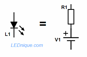
Figure 1. An LED can be approximated as a resistor with a fixed voltage source.

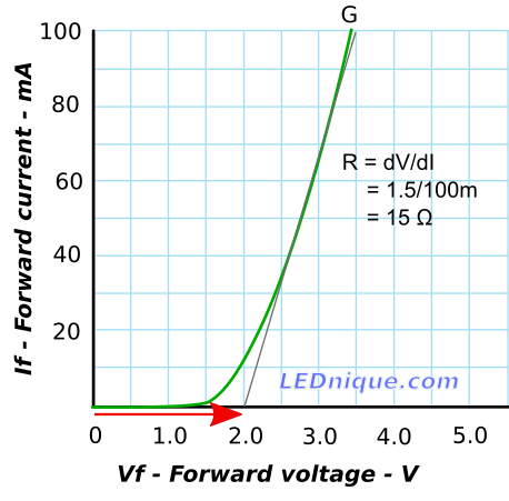
If we look at a typical LED IV curve we can see that it is approximately linear over much of its useful range. This allows us to model the LED as a resistor and voltage source.

enter image description here

Figure 2. LED equivalent circuit model.

In Figure 1 the grey line is reasonably close to the LED curve from 20 mA to 100 mA. We can work out the resistance that this represents from Ohm’s law V=IR but in this case we will look at the change in voltage and current in the area of interest.

$$R=\frac{ΔV}{ΔI}=\frac{3.5–2.0}{100m–0}=\frac{1.5}{100m}=15\ Ω$$

We can also see that the line crosses the X-axis at Vf = 2.0 V. Our equivalent circuit for this region of interest is (referring to Figure 2) R1 = 15 Ω and V1 = 2.0 V.

Compared with the parallel 100k resistors in your model, the 15 Ω resistor in my model is dwarfed and the LED will behave pretty much like a constant voltage source as you discovered.

Since you have a bench PSU and multimeter you can plot the I/V curve for the LEDs you have. I put together a slightly long-winded video for that on the IV-curves page.

\$\endgroup\$
3
  • \$\begingroup\$ So, pseudo-random actually ;) \$\endgroup\$
    – Wesley Lee
    Commented Nov 24, 2017 at 0:11
  • \$\begingroup\$ So, to be clear, the LED is NOT really self-regulating its resistance to get the voltage across it up to 3? \$\endgroup\$
    – ad555
    Commented Nov 24, 2017 at 11:17
  • 2
    \$\begingroup\$ It's kind of the other way around: you need to get the voltage up to about 3 to get the diode to "open" and conduct a significant current. Once this happens the voltage increases very slightly with large increases in current. See the link I posted in the comment to jonk's answer. \$\endgroup\$
    – Transistor
    Commented Nov 24, 2017 at 11:38
2
\$\begingroup\$

Forget all the fancy charts. It's actually pretty simple. If you have a device that requires about \$3\:\textrm{V}\$ across it and are applying \$120\:\textrm{V}\$ across it through a resistor, then you have a very good current source. So the LED itself won't matter that much. It's this simple:

$$I = \frac{V_{120\:\textrm{V}}-V_{LED}}{R}$$

This works out to:

$$\textrm{d} I = \left[\frac{-V_{LED}}{R}\right]\textrm{d}V_{LED}$$

So with \$R\approx 50\:\textrm{k}\Omega\$, this means that if \$\textrm{d}V_{LED}=1\:\textrm{V}\$, then \$\textrm{d} I=60\:\mu\textrm{A}\$. That's not a lot of change in the current for a full volt change in the LED voltage. A current of \$2.4\:\textrm{mA}\$ would become \$2.34\:\textrm{mA}\$, or else \$2.46\:\textrm{mA}\$, depending on a full volt change in the LED's required value. That's not a lot of variation.

In terms of percent, you'd compute:

$$\frac{\frac{\textrm{d}I}{I}}{\frac{\textrm{d}V_{LED}}{V_{LED}}}=\frac{V_{LED}}{I}\cdot \frac{\textrm{d}I}{\textrm{d}V_{LED}}=\frac{3\:\textrm{V}}{2.4\:\textrm{mA}}\cdot\frac{-3\:\textrm{V}}{50\:\textrm{k}\Omega}=-0.075$$

In short a 33% change in the LED voltage would result in \$-0.075\cdot 33\%\approx -2.5 \:\%\$ change in the current in the LED.

So that's pretty good regulation. The reason is mainly because of the huge resistor value you are using here. If it were smaller, the regulation would be poorer.


Another, separate reason to consider is that LEDs vary in their voltage based upon the Shockley equation:

$$I_{LED}=I_{SAT}\cdot\left(e^{\frac{V_{LED}}{n V_T}}-1\right)$$

Or,

$$\textrm{d}V_{LED}\approx \frac{n V_T}{I_{LED}}\textrm{d} I_{LED}$$

Here, with \$V_T\approx 26\:\textrm{mV}\$ and \$n\approx 2\$, you would expect about \$50\:\textrm{mV}\$ change in the LED voltage for a doubling of the current through it. That's not much of a voltage change for a fairly significant change in the current through the LED. And to get that kind of change, you'd have to double the current through \$R\$, too. And you know that cannot happen. So the result is that there is only a very modest change in the voltage across the LED even with a significant change in the current through it.

Those fancy charts are showing you this effect. And that would take over and explain things, if you had a much smaller voltage to drop. But in your case, even if it were not the Shockley equation but some other behavior instead, you'd still have good regulation because of that huge voltage you are tossing away. You'd have good regulation with a low voltage light bulb, too, for example. So while this effect would account for good regulation with a low voltage source, it isn't the reason here.


No curves required. It's just that you have a LOT of voltage headroom here and this accounts for good regulation.

If you need to see this another way, just imagine a huge voltage of \$1,000,000\:\textrm{V}\$ across a resistor of \$100\:\textrm{M}\Omega\$. The current will be \$10\:\textrm{mA}\$, right? Suppose you have an LED inserted there? How much would the current change if the LED needed \$10\:\textrm{V}\$ instead of just \$3\:\textrm{V}\$? Not much, right? Because the source voltage is so large, and because the dropping resistor must drop so much of the voltage, variations in the LED voltage have almost no effect at all on the current through the LED.

It's as simple as that.

\$\endgroup\$
12
  • \$\begingroup\$ Well, at least you though my chart was "fancy". :^) \$\endgroup\$
    – Transistor
    Commented Nov 24, 2017 at 7:35
  • \$\begingroup\$ @Transistor Nah. Wesley's chart was the fancy one. ;) \$\endgroup\$
    – jonk
    Commented Nov 24, 2017 at 10:11
  • \$\begingroup\$ @jonk Yeah, I figured that somehow it had to do with how massive the power source is. But I still don't get why the circuit stabilizes with 3v exactly across the LED. It seems very convenient and counterintuitive to me. So, my question is about whether the LED's properties are somehow managing this... \$\endgroup\$
    – ad555
    Commented Nov 24, 2017 at 11:29
  • 1
    \$\begingroup\$ @ad555: Are you comfortable with the notion of \$ V_f \$ or jonk's \$ V_{LED} \$, the forward voltage of the LEDs, which is what the maths and graphs are demonstrating? Have a look at my LED -> diode -> non-return valve analogy. \$\endgroup\$
    – Transistor
    Commented Nov 24, 2017 at 11:35
  • \$\begingroup\$ @ad555 Yes, the charts you were already provided (or the Shockley equation I chose to mention instead) provide this feature. The current regulation aspect is in large part because of the huge overhead voltage. But the voltage regulation at the LED itself is due to the Shockley equation behavior. It would take a 10-fold change in the current to yield perhaps \$100\:\textrm{mV}\$ change in the LED voltage. (The exact value depends on the emission coefficient and temperature.) So the LED voltage is pretty stable. \$\endgroup\$
    – jonk
    Commented Nov 24, 2017 at 11:35
1
\$\begingroup\$

Transistor nailed it in a comment. The LED isn't good at self-regulating, it's the opposite. The LED is so bad at self-regulating that it turns the resistor into a useful regulator.

An extreme example

Think about light emitters generally. Incandescents are linear, asterisk*. You know about LED, not very linear. Even less linear are the arc-discharge family (fluorescent, neon, sodium, mercury, halide) - insulators until the arc strikes, then a dead short. One thing all light emitters have in common is they would work pretty well driven constant-current.

So let's take a more extreme example. All you have is a 2400VAC distribution line over your junkyard, a 400W high-pressure sodium bulb and socket (ideally 4A@100V-ish), and a huge 1k ohm 20kw resistor. You wire it in series Line -- Resistor -- HPS bulb -- Line. What happens?

At resting state, the bulb resistance is infinity, 0 current flows, the resistor drops 0V, so 2400V presents at the socket. That happens to be the arc-strike voltage of a HPS bulb. Now the bulb is lit, and it's a dead short, or close enough to one.

Now that current is flowing and the bulb is trying to emulate a dead short, almost all voltage drop is in the resistor: E=IR 2400V=I*1000ohm. We are flowing at most 2.4 amps -5%. This is well within the working range of a 400W HPS bulb, so it's making probably 200-230 watts of jaundice yellow light. The bulb's desire to be a dead short is making the resistor a better regulator. Without the resistor, the bulb would meltdown even at a voltage near its operating voltage e.g. 120V.

This example isn't extreme because of the high voltage (it's only 24x working voltage instead of your 40x). It's extreme because discharge lights are so extremely bad at self-regulating.

Much the same with LED

Forget about all that complicated math (wink to Jonk here), the example above is the gist of it. The resistor is such a large impedance that even significant drift in the LED's characteristics (from binning, temp, age) is unlikely to change the math (if you could even call it math).

This works because the input voltage is such a large multiple of LED working voltage, that the resistor is doing all the work. If we were running much closer (3V LED on 12V or even 5V supply) then we need the sharp pencil and work it out in detail as Jonk and Transistor discuss.

Of course it's a waste to just burn up all that energy in a resistor. But running an incandescent bulb is not considered a waste, and they are linear. I have sometimes wondered about using an incandescent bulb as (effectively) the ballast for an LED or discharge light. They would complement each other, ones strengths helping the other's deficiencies.


* Unlit incandescents have very low resistance (nearly a dead short), their resistance increases sharply as they start to glow, settling at a relatively constant resistance through their working range. If you apply constant voltage to them, they surge current initially, this is called inrush current. This drives electricians nuts: you get that nice 20A control relay, and the fine print says "5A tungsten" owing to inrush current. Argh! On the other hand, if you drove incandescents constant-current, they'd be very well behaved indeed: removing the shock of startup power would extend their life significantly. And they'd be easier to provision, you could actually get 20A out of that relay. Unfortunately "tungsten rating" is here to stay, it also applies to electronic ballasts for discharge lighting and LED drivers... their startup also causes an inrush (charging caps etc.) You wouldn't think it would be that hard to switch a light on...

\$\endgroup\$
1
\$\begingroup\$

Congratulations. You've just discovered "band-gap". It's the energy range that no electron state exist. It's voltage is the needed potential to knock off electrons from their orbits on a massive scale so they could skim on the semiconductor and also to leave behind holes, which further allows in more electron to skim.

In NP silicon technologies, that band gap is about 0.7V. In LEDs, that band gap is tweaked so that the voltage at which Photoelectric Effect are at a specific voltage and thus specific quantizied energy for the photons and therefore wavelength and thereby color. Current controls the how much this happens and thus the brightness of the LED.

That's just about the physics I know about these things, as I am no physicist myself.

The problem with calculation methods in Electric Engineering is that they don't accept the presence of Piecewise functions in non-approximating mathematical models of the circuits. They think it's only like that when we're doing approximations and completely absent when doing Complex Analysis. That's true when dealing with passive circuits, where everything is linear (obeys Linear Transformations). Even what seems like Combinatorial change in current or voltage is simply resolved by sign conventions (it's not where current goes left or right, it's if it goes or leaves a single terminal of a component).

But it's a different world when it comes to "active" circuits. Piecewise functions really do exist there, whether you use approximations or very accurate complex functions. You can have 2 active devices in series whose equations say they will have different current through them and what ever you do you just can't make them agree or "converge" on a single current. You have to pick one. It's the minimum. Those SPICE simulations you trust so much? They already DO use Piecewise functions, or most of your digital circuit simulations will never converge and finish.

Because of this, your circuit above will have the current:

$$ I_T = I_s(e^(\frac{V_T - I_T R}{n V_t} - 1)) $$ It's the diode that controls the current here and yes, diodes are active components, as they break the singly defined linear equations.

So we simply have:

$$I_T = I_s(e^(\frac{V_T - I_T R}{n V_t} - 1)$$ $$I_T R = V_T - n*V_T*ln(\frac{I_T}{I_S} + 1)$$ $$I_T = \frac{V_T - n*V_T*ln(\frac{I_T}{I_S} + 1)}{R}$$ $$I_T = \frac{V_T - V_D}{R}$$

The only problem why it's not exact is that we use a fairly constant V_D of 0.7V, instead of always using \$n*V_T*ln(\frac{I_T}{I_S} + 1)\$. Then again the Shockley equation is ALSO an approximation, but you're free to use more complex equations.


ALSO, don't buy from Lees's Electronics, they might mistake to give you parts set aside for me and you might end up with faulty components.

\$\endgroup\$
3
  • \$\begingroup\$ This is also why I say you could just replace the \$V_{BE\_SAT}\$, \$V_{CE\_SAT}\$, etc by their derivations of \$V_{BE}\$ and \$V_{CE}\$ from Eber-Molls equations, etc. \$\endgroup\$
    – Dehbop
    Commented Nov 25, 2017 at 9:37
  • \$\begingroup\$ At insulting greeting from earlier: Wow, what's your problem Dehbop!? Seriously. >.> \$\endgroup\$
    – ad555
    Commented Nov 25, 2017 at 11:49
  • \$\begingroup\$ Also, I already know about minimum forward voltage -- which is essentially what the "band gap" you're talking about is. I even mention that in my question. \$\endgroup\$
    – ad555
    Commented Nov 25, 2017 at 11:50
0
\$\begingroup\$

I wouldn't do that in a production model. LEDs aren't rated for 120VAC (170V peak) reverse voltage. The only thing that keeps the reverse voltage sane on LED1 is the fact that LED2 is functioning and keeping the voltage at 3v. If LED2 has a problem, suddenly LED1 is looking at 170V peak reverse current, kaboom.

Series each LED with a diode good for 170V peak reverse current.

That said, I plan to do exactly this with 75VDC, which is even more feisty than 120V AC, but reverse current is not an issue in that case.

\$\endgroup\$
3
  • \$\begingroup\$ The reverse voltage goes thru the opposite LED, which is actually a fairly common (albeit shady) design. Why would you expect one of the LEDs to have a problem? They seem to protect each other quite well. \$\endgroup\$
    – ad555
    Commented Nov 24, 2017 at 11:23
  • \$\begingroup\$ @ad555 I know, I'm suggesting you engineer for the day it doesn't. Products fail. Presuming this is going to live more than a day... if it's just a breadboard "what happens if" test, then nevermind. I don't think this could get past UL into a consumer product, or else every LED nightlight would be exactly this. \$\endgroup\$ Commented Nov 24, 2017 at 15:30
  • \$\begingroup\$ Fair enough. But as you suspected it's just a little breadboard experiment, and I'm honestly scared to leave it running, in case it catches the house on fire. If I were going to do a proper thingy, I'd use a proper capacitive dropper with a single-diode rectifier. (For a power indicator.) And if I were going to make a nightlight, I'd turn that into a full bridge. :P \$\endgroup\$
    – ad555
    Commented Nov 24, 2017 at 23:42

Your Answer

By clicking “Post Your Answer”, you agree to our terms of service and acknowledge you have read our privacy policy.

Not the answer you're looking for? Browse other questions tagged or ask your own question.