14
\$\begingroup\$

I'm trying to build a frequency modulated LC oscillator but all circuits I've tried have terrible mains hum after demodultaion.

The oscillator is tuned by capacitive sensor but I'm using a fixed capacitor instead until I solve this problem. I've tried different topologies: Franklin, Clapp, Vackář, Hartley at different frequencies from 60 to 500 MHz but there's no difference between them in terms of mains hum. I'm using an SDR receiver for demodulation, it works fine and cannot be the source of hum. Using battery instead of AC supply didn't help. I`m using 10 µF and 10 nF capacitors for decoupling. Using physically smaller inductors helped a little, but the noise is still unacceptable.

As suggested in comments, I've tested all circuit nodes with and without powering the circuit and 50 Hz component appears only at the antenna output.

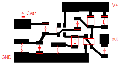
Here are some PCB drawings, maybe there are mistakes in routing?

Fig. 1: Vackář topology, the transistor is BF545C

Fig. 2: Franklin topology, both transistors are ATF-38143
[UPD:]

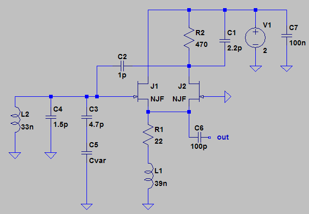
Uploading my setup and schematics as requested. The setup is just an SDR receiver and the oscillator with a piece of wire at the output as a makeshift antenna. The capacitive sensor Cvar is absent, as I'm using a fixed capacitor C4 instead.

Fig. 3a:
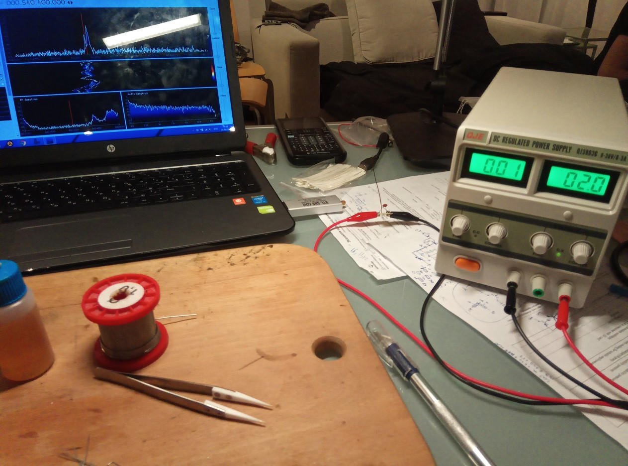
Fig. 3b:
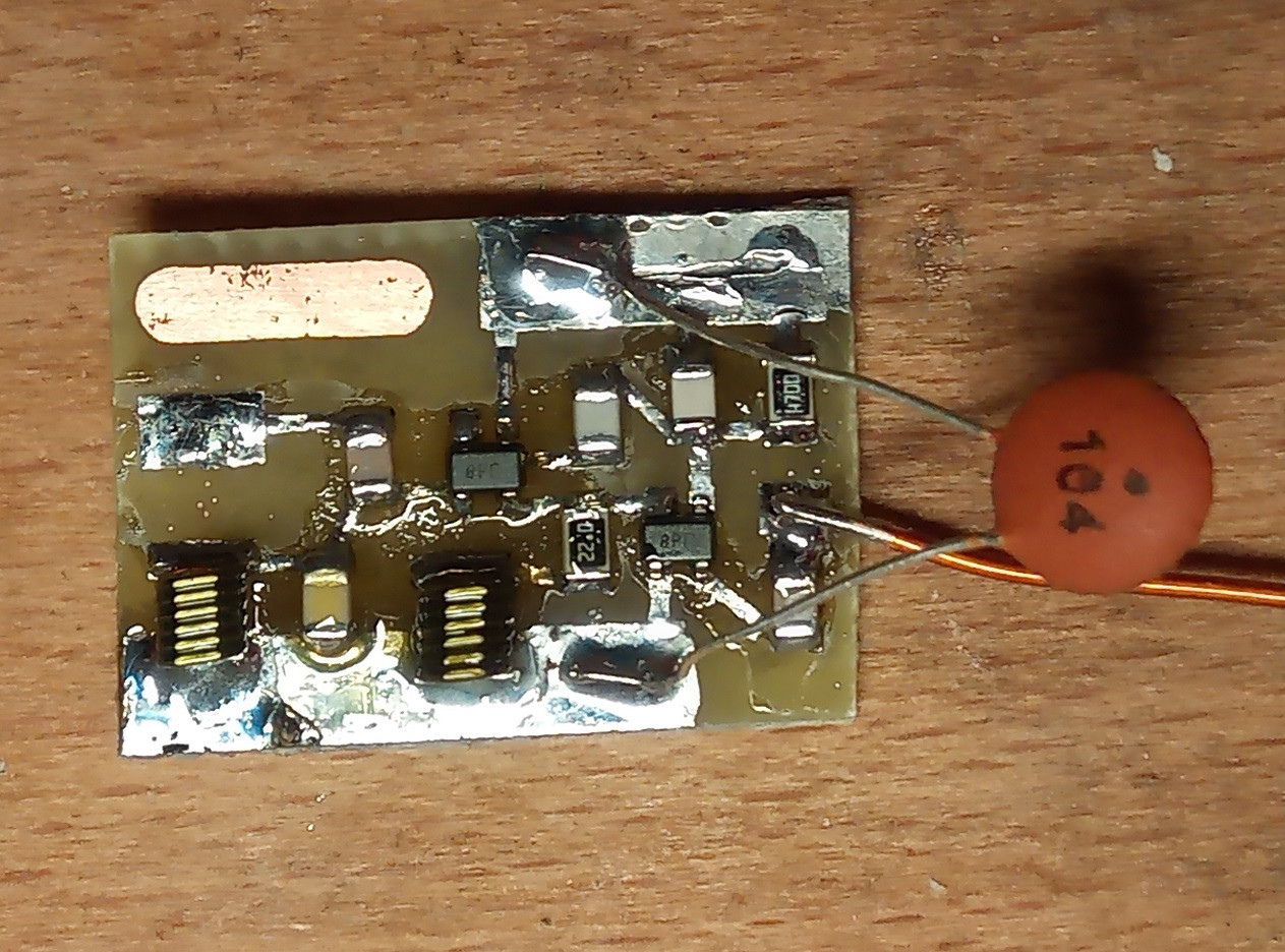
Fig. 3c:
[UPD2:]

SNR at 50 Hz is 4.3 dB. Maximum frequency deviation for Franklin oscillator is 290 kHz, output power is 7.8 dBm, received signal level is –26 dBFS. Grounding the laptop makes no difference.

[UPD3:]

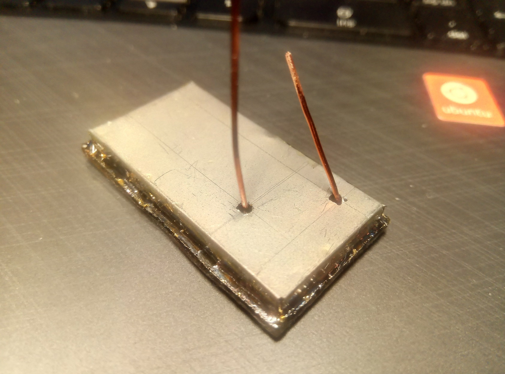
I've made a new board with a ground plane and a nickel silver EMI shield. I've added a 1.8V LD1117 regulator and 100pF and 390pF NP0 decoupling capacitors — and still no luck. There are no significant changes in the noise performance. Unfortunately, I couldn't find an iron box to put the whole circuit in, but I'm almost sure there are some clever circuit and PCB design techniques that do not require magnetic shielding. For example, I've tested the SDR receiver on a cheap unshielded FM transmitter: there's no hum at all, even with the volume maxed out, so the culprit is definitely the circuit and PCB design.

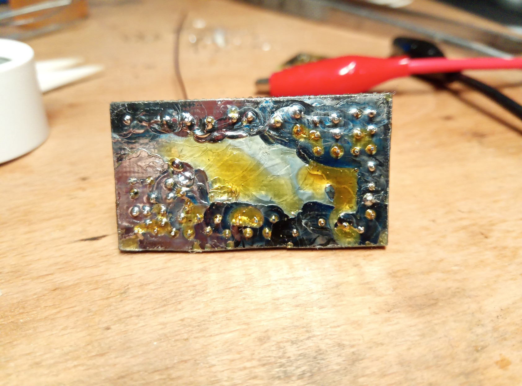
Here are some photos of the board (sorry for the flux, I did try to remove it but failed)

Fig. 4a: enter image description here

Fig. 4b: enter image description here

Fig. 4c: enter image description here

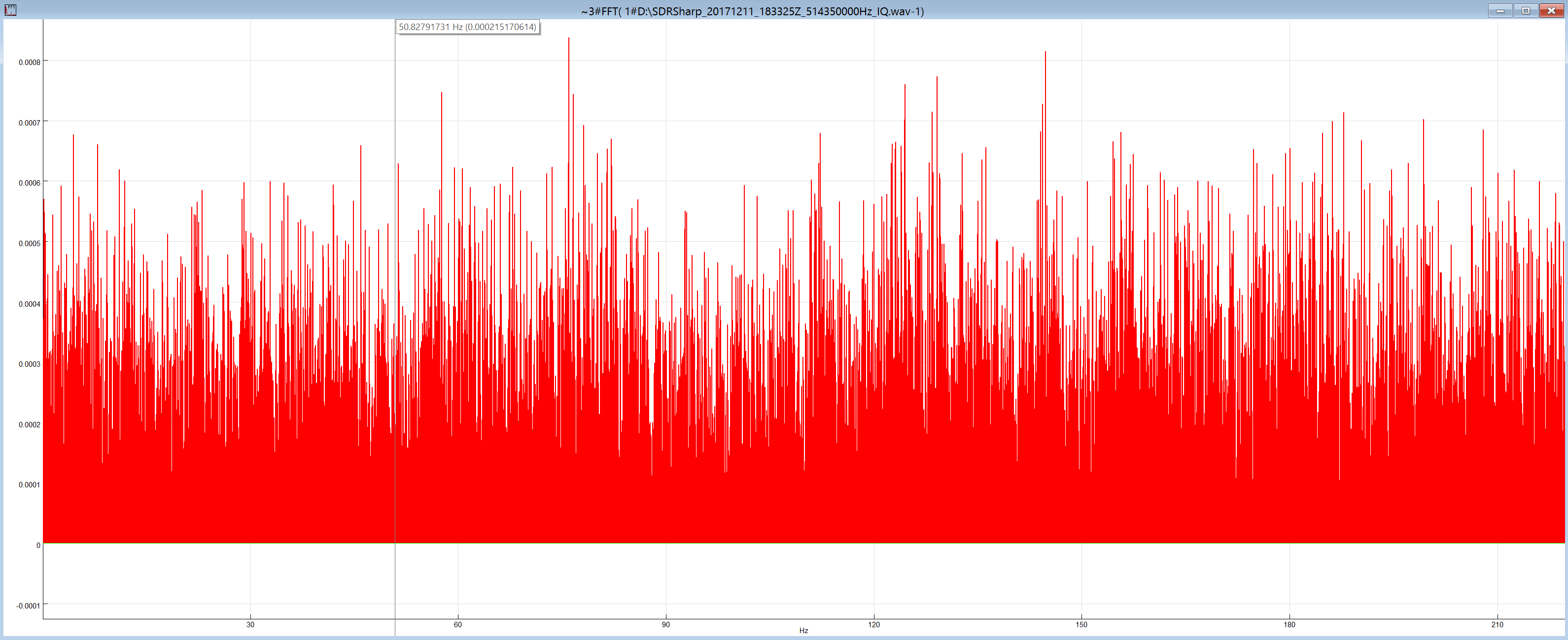
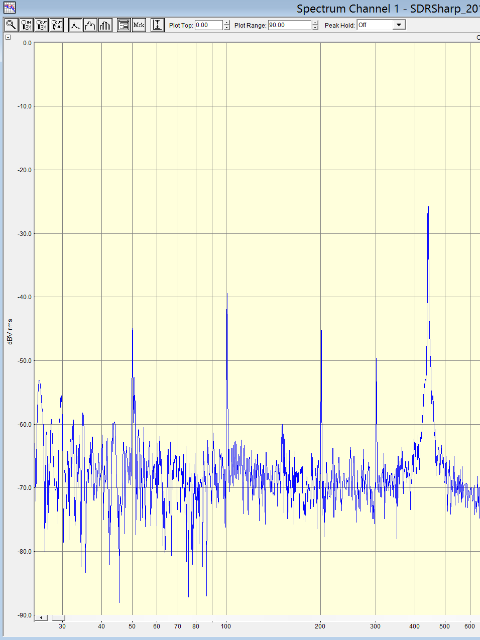
Also, as suggested in the answer below, I've recorded an IF from my SDR receiver and generated its spectrum at low frequencies.

Fig. 5a: Without the EMI shield enter image description here
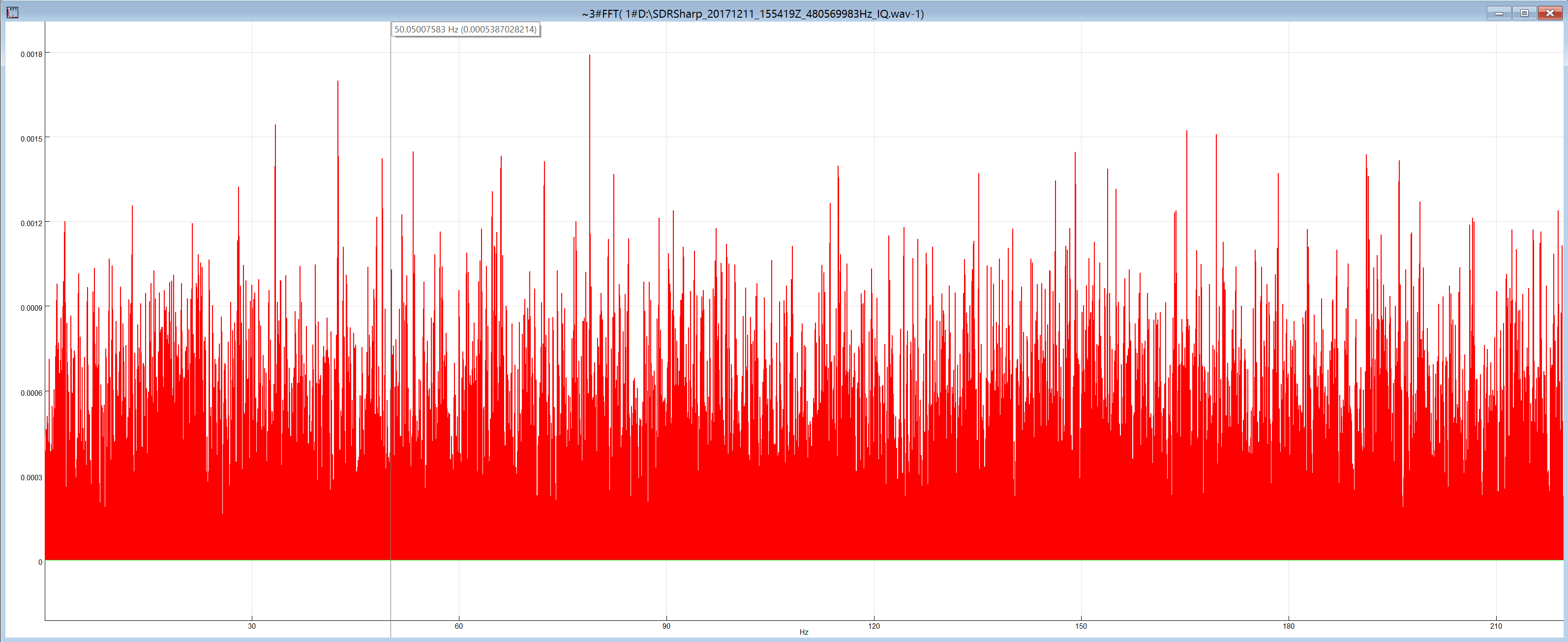
Fig. 5b: With the EMI shield enter image description here

[UPD4:]

Now that is interesting.

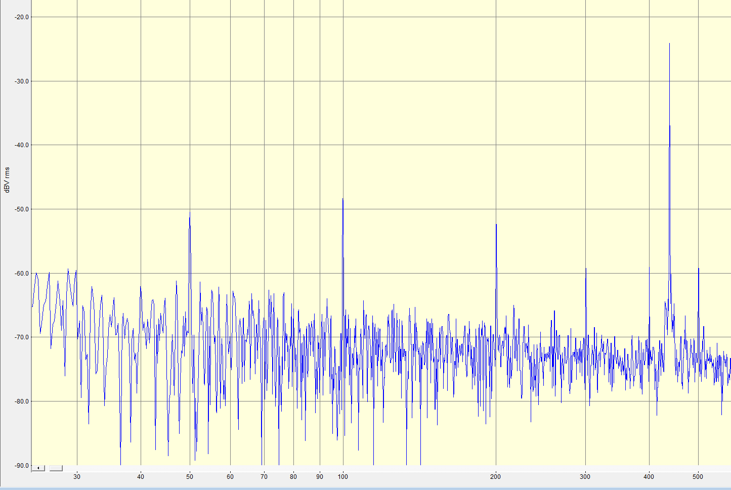
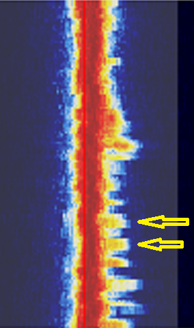
Increasing C4 (see Fig. 3c) reduces the noise significantly. Look at the demodulated signal spectrums (the 440 Hz component is a test signal recorded from the sensor for SNR measurement):

Fig. 6a: C4 = 1.5 pF enter image description here

Fig. 6b: C4 = 2.7 pF enter image description here

Unfortunately, I've got no other capacitors in the range between 1 and 10 pF to make further tests (the oscillator won't start with C4 ≥ 10 pF). I guess that the AC line noise picked by PCB traces and L2 changes the gate capacitance of J1, and increasing the value of C4 reduces the influence of those changes on frequency. This is also confirmed by adding a strong noise source, e.g. a cell phone making a call. You can see large spikes on Fig. 6c and the frequency does actually increase when I add a noise source, meaning that the gate capacitance of J1 is inversely proportional to voltage. Makes sense to me. Seems like I need to either reduce coupling between J1 and LC tank or add some high-pass filtering between them, but I'm not sure what the best way of doing it is.

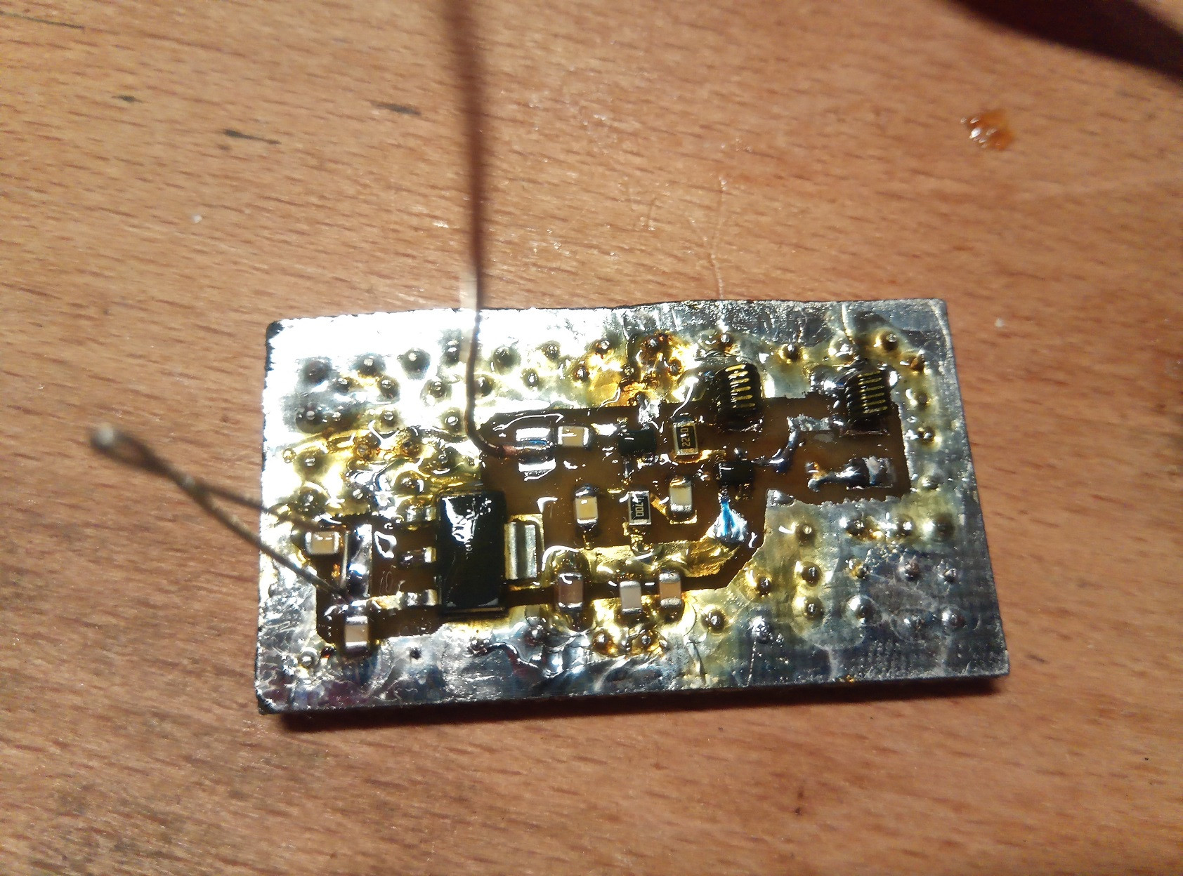
Fig. 6c: enter image description here

\$\endgroup\$
37
  • 1
    \$\begingroup\$ "Using battery instead of AC supply didn`t[sic] help", this should tell you something. \$\endgroup\$ Commented Nov 26, 2017 at 15:12
  • 2
    \$\begingroup\$ And for the future, seeing ` being used as ' is like hearing someone call coolwhip for coolHwip. I won't be the last one to tell you this. - If I did something strange in a public domain without knowing it, then I'd appreciate if someone told me. This is me being that someone for you. \$\endgroup\$ Commented Nov 26, 2017 at 15:55
  • 2
    \$\begingroup\$ I'm no antenna theorist, so I'm out on deep waters right now, but I do know how to debug things. - You read mains while being encapsulated by mains cables (you're indoors), it's not that super weird. With this said, do you still read mains signal even when the bench supply is off (not sending any data)? - This will probably be my last comment since I'm pretty unfit for this question. Just getting as much information as I can so when the proper antenna users come along, they will say "Hah! His flux capacitor is broken, look at that Marty, he won't be able to go back to the future!". \$\endgroup\$ Commented Nov 26, 2017 at 18:28
  • 1
    \$\begingroup\$ Mains hum, if the circuit is battery-powered, can only come from injected magnetic or electric fields. Or the circuit is oscillating at some frequency that looks like mains 50/60Hz. \$\endgroup\$ Commented Nov 26, 2017 at 19:49
  • 2
    \$\begingroup\$ With a circuit of this type, I am not sure you can get away with a single-layer layout if what you are experiencing is inductive pickup from mains. There are loops in your circuit layout that can result in a mains-related induced current. I might try seeing if rotating the board causes changes in your amplitude. A ground and possibly a power plane might help with decoupling caps. If not you will need some shielding. \$\endgroup\$ Commented Dec 7, 2017 at 20:55

4 Answers 4

4
+500
\$\begingroup\$

Gomunkul (in comments) & @user287001 may have nailed most of the hum problem:

It's probably your probe or the antenna that catches the hum from the air because the capacitor is an open circuit for 50Hz.

C6 may be a poor-quality capacitor that varies capacitance with voltage:

  • Use a good C0G capacitor here (100 pf is likely too much) or one rated for microwave.

  • Terminate the antenna with a resistor-to-ground, to reduce the electric field across C6 induced from nearby 50 Hz appliances, lights.

  • Add a buffer stage with nice low S12 between oscillator and antenna.


There is another possible hum mechanism, somewhat less likely....
This oscillator with antenna can be considered a crude direct-conversion receiver: its oscillations serve as the receiver's local oscillator. With such low-voltage DC bias voltages, this oscillator's active device junctions may have significant capacitance variations with changes in voltage. Where a junction sees both transmitted signal (strong) and received signal (weak), its bias voltage can vary, depending on the phase relationship between the two signals.

Far away, some diode junction(s) may receive some transmitted signal from your oscillator. Where these junctions are also turned on & off while rectifying 50 Hz mains, they re-transmit a 50 Hz. modulated signal back to the oscillator via wires or traces. At UHF, even a short wire becomes a coupled antenna element in this 2-element system. The 50 Hz modulated diode may inject a phase change back at the oscillator. It is characteristically full of harmonics, since those 50 Hz modulated diodes switch from on-to-off fairly rapidly. Your spectrum's 50 Hz harmonics seem quite strong.
DC power supply rectifying diodes are often the source.
LED lighting circuits could be another source.
Your cell-phone shifting frequency also supports this theory.

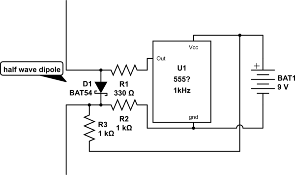
You might test for this phenomenon with the following (incomplete) circuit:

schematic

simulate this circuit – Schematic created using CircuitLab


The half-wave dipole is cut for the oscillator-under-test's UHF frequency. Its diode connects between each 1/4 wave element. A 1kHz function generator could be used to turn the diode on-and-off rather than a 555 1 kHz oscillator. When this "mosquito" circuit is coupled to the transmitter's antenna, a monitoring receiver (AM PM or FM) may detect the 1kHz signal. Moving this "mosquito" circuit away from the oscillator-under-test should reduce the monitoring receiver's audible output.

An aside: this same coupling mechanism is sometimes present in doppler radar, and motion-detecting theft alarms. In this case, phase changes as the reflecting signal distance varies from the UHF signal oscillator.
You may get more insights by googling "tune-able hum" or tunable hum.

\$\endgroup\$
1
  • 1
    \$\begingroup\$ Woohoo! Adding the output buffer and decreasing C₆ to 2.2 pF eliminated the noise completely. Thank you so much! \$\endgroup\$ Commented Dec 16, 2017 at 21:29
4
\$\begingroup\$

You schematic is inaccurate in the real physical model so it won't work as expected in your schematic.

For example your decoupling 0.1uF cap is about 20nH in the 2 leads of 2cm and 1mm thickness (est) and 1cm track length. Meanwhile your resonator uses 33nH , so your supply has poor impedance and as others suggest perhaps 100pF in a small SMD cap is needed. The overall layout is too big without a ground plane and therefore has a large loop antenna area for radiating and receiving stray electric fields.

I agree most of your hum is due to the large layout >5% of a wavelength for supply, ground and circuit loop path. This makes is prone to radiated noise and conducted ground noise. Using an RF CM balun or RF CM choke is essential for your DC supply to decouple it from AC grounds in addition to an RF cap preferably a 100pF NPO cap for lowest ESR.

Without a super narrow IF band Spectrum Analyzer (<100Hz) to examine AM vs FM , it is impossible to tell how much noise is in your SDR and how much is in the Tx. But either way the hum is mostly in your LCO design and DC power/return paths. If you had a lab RF gen. , then you can validate your SDR and a good RF SA to validate your noise source.

When we made VCO's in the mid 90's for 928 MHz ISM band for we made custom ceramic hybrids with custom metal lids seam soldered over the hybrid soldered to a GETEK FR4 substrate with another ground plane > 60 dB CNR ( carrier to noise ratio and low phase noise for a 6kHz Tx bandwidth used for automated 2 way meter reading.

  • Dielectric constant, substrate loss tangent and shield capacitance all played a role in the design and I recall at the time 603 size 47pF NPO with 2 stage RC LPF were used to reduce supply noise to get down to 10 Ohms then used a design with low supply sensitivity with current sources unlike this one. Now Murata makes low ESL caps of 100pF or more to cover this spectrum that are wider than long.

lessons to learn

  • How to calculate and measure inductance, ESL and ESR of tracks wires and passive components.
  • How to validate RF with a SA to isolate root causes of noise.
  • How to discover how critical layout with options for ground planes , stripline , microstrip and cover shields to minimize interference using waveguide theory, controlled impedances, crosstalk and antenna sensitivity - How to measure return loss measurement techniques and how to improve spectral purity with higher Q resonators and low Q supply decoupling with CM rejection.
  • This is just a start and the expertise is what makes good RF design Engineers worth more than others. ( I don't consider myself one, but I have learned from the best to know. )

Final words

If you master Ohms Law for RF using calculators for impedance of tracks, wires and coupling capacitance between stripline, you can understand better how to use a Balun to raise CM impedance then attenuate with shunt loads while controlling the differential impedance. This applies to 1GHz PHY networks as well as your Oscillator designs so you can observe similar designs to see these features and apply impedance ratios and Q of resonator to control the resulting SNR. It's all in the complex impedance ratios like a 2 dimensional version of Ohm's law with reactive impedance, then it starts to look simpler with antenna aperture effects. (Directional loop antenna)

\$\endgroup\$
7
  • \$\begingroup\$ I`ve updated the post and added the spectrum, but I`m not sure if I made it correctly. Unfortunately, I made the new board before you posted the answer, will try to find some CM chokes and see if they help. \$\endgroup\$ Commented Dec 11, 2017 at 20:51
  • \$\begingroup\$ I can't believe you do not understand antenna aperture effect of signal/wavelength aperture ratio. Why are you looking for baseband 50Hz on the SDR when it is on the modulation. you could examine AC coupled DC or 50Hz IF bandwidth of carrier \$\endgroup\$
    – D.A.S.
    Commented Dec 11, 2017 at 22:42
  • \$\begingroup\$ How tight is your Faraday shield? for resistance and slots? \$\endgroup\$
    – D.A.S.
    Commented Dec 11, 2017 at 22:51
  • \$\begingroup\$ There must`ve been a misunderstanding. I did actually examine the 455 kHz IF at a carrier of 480 MHz and then of 514 MHz; the frequency changed after I added the EMI shield. I posted the result in my third question update: there is an IF spectrum from DC to 220 Hz, see the pictures (#1: i.sstatic.net/188et.png, #2: i.sstatic.net/zlxKv.png). WRT the Faraday shield, it only has 2 slots, which you can see on the picture I also added to the question. The resistance is below my multimeter range (0.1Ω to be precise). \$\endgroup\$ Commented Dec 12, 2017 at 0:30
  • \$\begingroup\$ Ok thanks. The above photos only show white noise with one a few dB lower than the other. So 50Hz hum gone now with ground plane "donut"? What needs to be fixed now? \$\endgroup\$
    – D.A.S.
    Commented Dec 12, 2017 at 4:44
2
\$\begingroup\$

If smaller coils help, your circuit probably catches magnetic fields. They can be quite strong near transformers or fluorescent lamps.

Your sensor cannot be elsewhere than in your circuit board at 500MHz. I guess it senses acceleration, humidity, some gas or pressure. You probably can put your circuit into a thick soft iron box which short circuits the external magnetic fieds even when having some holes for the needed connection to ouside air. You need a local voltage regulator to keep the AC fields out of the 2VDC operating voltage.

Sync your scope to mains AC and see, is the hum stable in the scope screen. If it's not, your circuit oscillates itself at about 50Hz.

Test also, is your circuit mechanically microphonic. I have made a transmitter which (unwantedly) picked quite weak vibrations.

You wrote "50Hz AC is present only at the antenna output" It's probably your probe or the antenna that catches the hum from the air because the capacitor is an open circuit for 50Hz.

The mains hum+harmonics also can be filtered out from the demodulated signal by filtering software. The filtering is essential for example in brain or heart tests and cleaning the audio signals.

Test your receiver with another transmitter. Is the receiver itself hum-free.

\$\endgroup\$
0
\$\begingroup\$

I understand an oscilloscope is expensive(unless you live in US. I've seen a lot of cheap scopes going to 500 MHz or so on ebay). You should get a signal generator and a milivoltmeter for those frequencies(you might be ok with a SDR for milivolmeter, depending on what you have). From the pictures you attached I suspect the oscillator doesn't work at all. That's not what a sinusoid looks like (be it 400MHz or 50Hz, a sinusoid is a sinusoid). Whatever shape you got there is so ugly you can't even name it. Try to analyze it in two steps: first step, make sure you can amplify a signal in that range. Second step: check what your tuned feedback does in that range. Yes, you need a signal generator for that. You might use the SDR as milivoltmeter/scope, but you do need a signal generator. Had you had hum, it should either 1)be gone on battery power supply or 2)be present even after you remove the battery.

\$\endgroup\$
1
  • 2
    \$\begingroup\$ When you say that the oscillator isn't working, and, "Whatever shape you got there is so ugly you can't even name it", what do you mean? Which figure are you referring to? The images are frequency domain plots, not time domain. \$\endgroup\$
    – Daniel
    Commented Dec 16, 2017 at 4:17

Your Answer

By clicking “Post Your Answer”, you agree to our terms of service and acknowledge you have read our privacy policy.

Not the answer you're looking for? Browse other questions tagged or ask your own question.