1
\$\begingroup\$

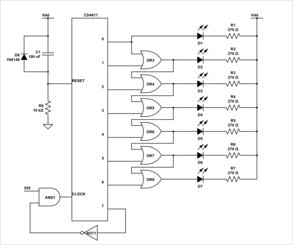
I'm in the process of turning a Raspberry Pi project into a simpler circuit board powered with 555 and 4017 chips.

I want to be able to start by showing 7 LEDs, then go to 6 then to 5 and so on until all are dimmed.

I'll take a simple example with 3 LEDs: LED 1 lights if the board is in state [0]. LED 2 lights if the board is in state [0 OR 1]. LED 3 lights if the board is in state [0, 1 or 2]. Nothing is connected to the board for state [3]. Thus in the board's state of 0, LEDs 1, 2 and 3 light. In state 1, LEDs 2 and 3 light. In state 2, only LED 3 lights. In state 3, nothing lights.

I had tried using the step by step outputs of the 4017 chip and diodes to form an OR circuit, but I think I have all the LEDs in series (draining too much voltage) so the resultant brightness with more than a couple of LEDs is terrible.

Question 1: How can I have the LEDs counting down (AND with good voltage to the LEDs when they are lit), as above?

Question 2: The LEDs are just one half of the circuit board. How can I make sure that once the 4017 chip enters its eighth state, the LEDs STAY off (until the circuit board's power is turned off and on again)? The examples I'm finding on the web seem to circle continuously. Thanks.

\$\endgroup\$
4
  • \$\begingroup\$ With just those two ICs you will struggle with this task, you will need some extra logic. It would be cheaper. smaller, neater, and easier to accomplish this with a small microcontroller. \$\endgroup\$
    – Colin
    Commented Nov 27, 2017 at 9:18
  • \$\begingroup\$ Thanks @Colin__s. Are there particular microcontrollers you'd suggest I look at? \$\endgroup\$ Commented Nov 27, 2017 at 10:19
  • \$\begingroup\$ I haven't used them, but for a one off something like Arduino would probably be good. There's a fairly easy entry path, and a large support community. If it's something you're planning to make in volume and monetise then the smallest cheapest micro you can find with enough IO, or a smaller cheaper micro and a shift register if that's cheaper. \$\endgroup\$
    – Colin
    Commented Nov 27, 2017 at 11:20
  • \$\begingroup\$ ATTiny. I used an ATTiny85 running on internal oscillator, powered off 2 AA batteries for exactly this - using 5 LEDs in my case. Only components were the LEDs, a reset button (to reset the timer) one resistor (for the Reset pulldown) and the ATTiny. And obviously a ISP programmer. Nice thing about running it off 2 AAs is that you don't need current limiting resistors. I used one red, one yellow and three red LEDs for a shower count-down timer. \$\endgroup\$
    – RJR
    Commented Nov 27, 2017 at 11:47

2 Answers 2

1
\$\begingroup\$

There are many ways to do this, some include a bag of diodes.. or a micro, which would be overkill in my opinion.

The simplest is just to cascade some OR gates.

schematic

simulate this circuit – Schematic created using CircuitLab

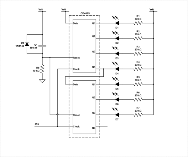
However : If that is all these outputs are being used for, you are using the wrong part here. You should consider using a shift register instead. Perhaps a CD4015.

schematic

simulate this circuit

NOTE: Resistors shown are for 5V Vdd.

\$\endgroup\$
0
\$\begingroup\$

I did this for 5 leds using an ATTiny85, a reset button with 10k pulldown, and 2x AA batteries for power. No current limiting resistors required (due to the voltage of the two AAs). In theory you could use the reset pin for a 6th LED, but then you'd have to use the power switch to reset the controller. Arduino Sketch:

// Shower timer with LEDs
// everything happens on the setup part.
// timer starts when reset
// once loop() is reached, go in deep sleep

#define LED1 0 // 1st green led
#define LED2 1 // 2nd green led
#define LED3 2 // 3rd green led
#define LED4 4 // yellow led
#define LED5 3 // red led

#include <avr/power.h>
#include <avr/sleep.h>

// the setup routine runs once when you press reset:
void setup() {
  // go low power
  power_adc_disable();
  power_usi_disable();
  power_timer0_disable();

  // initialize the digital pin as an output.
  pinMode(LED1, OUTPUT);
  pinMode(LED2, OUTPUT);
  pinMode(LED3, OUTPUT);
  pinMode(LED4, OUTPUT);
  pinMode(LED5, OUTPUT);
  PORTB = B00011111; // all LEDs on
  delay(60000); // one minute
  digitalWrite(LED1, LOW);
  delay(60000); // one minute
  digitalWrite(LED2, LOW);
  delay(60000); // one minute
  digitalWrite(LED3, LOW);
  delay(60000); // one minute
  digitalWrite(LED4, LOW);
  delay(60000); // one minute

  // blink for a minute
  for (int i=0; i<30; i++) {
    PORTB = 0;
    delay(1000);
    PORTB = B00011111;
    delay(1000);
  }
  PORTB = 0; // all off
}

// the loop routine runs over and over again forever:
void loop() {
  cli(); // disable all interrups
  set_sleep_mode(SLEEP_MODE_PWR_DOWN); // lower power sleep mode
  cli(); // disable all interrups
  sleep_enable(); // enable sleep
  sleep_cpu();  
}

To program the ATTiny 85, see http://www.hobbytronics.co.uk/arduino-attiny for example.

\$\endgroup\$

Your Answer

By clicking “Post Your Answer”, you agree to our terms of service and acknowledge you have read our privacy policy.

Not the answer you're looking for? Browse other questions tagged or ask your own question.