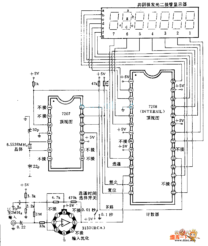
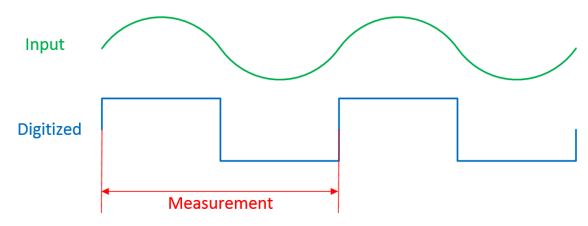
Generally you're going to convert the sine wave into a logic-level square wave.
Here is a very old schematic illustrating one way of doing it- the CA3130 op-amp is used as a comparator with about 50mV of hysteresis which squares up the input waveform and prevents noise from adding counts. The input is AC-coupled through the 220nF capacitor and the other resistors and 1uF capacitor bias the inputs within the common mode range of the amplifier and some measure of input protection is provided by the 33k resistor.

Because it is AC coupled, a waveform of more than 50mV p-p is all that is required, so about 18mV RMS.
The gate time is a fixed time, say 1 second or 0.1 second, and a simple frequency meter counts the edges (either rising or falling, but not both) that occur within that time. For example, with a 1 second gate if you count 50 edges the frequency is 50Hz. The count can be latched at the end of the gate period and sent to the display, and the counter can be reset to 0.
Some more sophisticated frequency meters measure the time between some number of edges and calculate the frequency. For example, if it takes 166.67 ms for 10 edges, the frequency is 60Hz.


