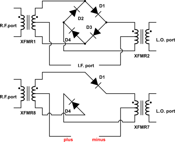
Top circuit shows the DBM unbiased. All four diodes are off and do not conduct. The R.F. port is isolated from L.O. port, as much as the balance of the transformers, diode parasitics allow. A well-balanced DBM might have 60 dB of isolation in this case. Note that signal amplitude cannot be so large that the diodes conduct on peaks.

simulate this circuit – Schematic created using CircuitLab
The second circuit shows Diodes D1, D4 biased ON via DC current that flows through the I.F. port. Diodes D2, D3 are biased OFF and conduct no current. In this case, the R.F. port is connected to L.O. port.
With a current source, diodes D1, D4 have internal resistance - combined with the 50 ohm R.F. port source resistance, and 50 ohm L.O. load resistance, you have attenuation. A stronger current provides less attenuation between ports.
It is important to apply a DC current source to the I.F. port, with a high-enough impedance that the R.F. signal passing through those diodes sees approximately the same current throughout the R.F. signal cycle, otherwise you get harmonic distortion. The impedance of the I.F. port should be at least ten-times that of the R.F. & L.O. ports.
Note that you can reverse the I.F. port current, and get signal inversion between R.F. port and L.O. port. via D2, D3.

