2
\$\begingroup\$

I'm having a bit of trouble with my Feather HUZZAH ESP8266 and a airsoft DC motor (similar to this one).

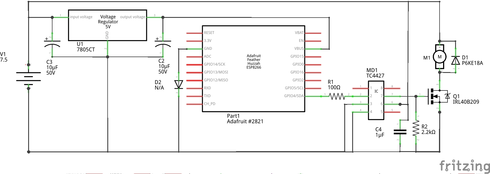
This is my circuit: enter image description here

I want to use Pin 4 on the ESP8266 to turn the DC motor on and off at 0.5 second intervals through the IRL40B209 MOSFET. Acknowledging that the MCU can only output 3.3V the GPIO pin, I am using a TC4427 MOSFET Driver to bring the signal up to Vcc (7.5V at 2A). The MCU is on a 7805CT voltage regulator, while M1 pulls directly from the power supply. The power supply is a Philmore Multivoltage regulated power supply set to 7.5V.

Unfortunately, once M1 turns on, it won't turn off, even with the pulldown resistor at R2. Once it's turned on, it goes full power and nothing short of pulling the gate wire out or shutting off the power will stop it. On my multimeter it shows that the data pin doesn't go logic low after M1 turns on. I think the motor is interfering with the MCU when it turns on.

What can I do to make sure that the motor turns off when the MCU goes low?

(P.S. Note that the above behavior does NOT occur while the MCU is plugged into my computer. The code is written in Micropython and I originally tested it while the MCU was plugged in and the code run through the webREPL. The circuit works exactly as intended while plugged in USB. A test with my multimeter also showed that the logic low voltage was lower while plugged into my computer (0.055V) vs when it's running off the power supply through the MCU's voltage regulator (0.885V).

EDIT: While on the Philmore power supply, once the motor is turned on, the ESP8266 stays at logic high 3.3V even though it is programmed to go low after 0.5 seconds, as measured by multimeter at the output for pin 4 between the resistor and the MOSFET driver. This behavior does NOT occur while the ESP8266 is connected to my PC by USB cable.

\$\endgroup\$
7
  • \$\begingroup\$ Philmore Multivoltage regulated power supply 'Provides constant current from 0-2000mA'. I bet the motor draws more than 2A. "the logic low voltage was lower while plugged into my computer (0.055V) vs when it's running off the power supply through the MCU's voltage regulator (0.885V)" - where did you read that voltage? You may have a 'ground loop'. Post a photo of your setup, showing power wire routing. \$\endgroup\$ Commented Dec 20, 2017 at 23:40
  • \$\begingroup\$ @BruceAbbott, I measured those values with my multimeter at the MOSFET driver's output pin. This is all on a breadboard, so it's not the tidiest thing to look at. I've made sure that no lines are running where they aren't supposed to be. Also, the motor is definitely trying to pull more than 2A. Airsoft motors are rated to run on as high as 30A. \$\endgroup\$ Commented Dec 21, 2017 at 1:20
  • \$\begingroup\$ @BruceAbbott My mistake, I measure BEFORE the motor driver input, not at the output. \$\endgroup\$ Commented Dec 21, 2017 at 1:26
  • \$\begingroup\$ @DevilMayTry - I've deleted my answer, as I had wrongly guessed the differences between the "working" and "not-working" configs. IMHO it would be helpful to update the question to clearly explain those. The differences in the voltages that you measured in those 2 configs, are vital to understanding the problem IMHO. However without doing my own tests, I don't have a better hypothesis yet about the cause. Your comment above that the motor is definitely trying to draw >2A is a problem when using a 2A power supply, of course, whether or not it's related to the issue you describe. Good luck! \$\endgroup\$
    – SamGibson
    Commented Dec 21, 2017 at 1:43
  • \$\begingroup\$ @SamGibson, Thanks for your answer. It gave me a place to start looking at least. \$\endgroup\$ Commented Dec 21, 2017 at 1:46

1 Answer 1

1
\$\begingroup\$

Well, I figured out a solution, though I'm not exactly sure if it's the right one just yet.

I swapped out the Microchip TC4427 MOSFET driver in the above schematic for a ON Semiconductor MC34152. I ordered a few units of both drivers a while back, during the planning phase of this project. I swapped the TC4427 for the MC34152 thinking there would be no difference in performance, but it turns out that the MC34152 has a different internal design that somehow works better in motor applications.

The difference maybe in the varied hysteresis between the two ICs. The TC4427 offers 300mV of hyteresis between the high and low thresholds on the input, while MC34152 offers 170mV of hyteresis. Also, the MC34152's datasheet explicitly details internal 30K ohm pulldown resistor on each input and 100k ohm pulldown resistors on each output. These may prevent the "latch up" behavior I was experiencing before on the TC4427.

Either way, it works as intended now at 7.5V 2A output from the power supply. Time to see if the same can handle 7.4V 30A from a LiPo battery.

\$\endgroup\$

Your Answer

By clicking “Post Your Answer”, you agree to our terms of service and acknowledge you have read our privacy policy.

Not the answer you're looking for? Browse other questions tagged or ask your own question.