0
\$\begingroup\$

I visit my father's house a few times each year. When he built the place, he had it wired for sound using in-wall systems, but (it seems) not by professionals. He blew out a receiver/amp, so I asked him to examine the wiring and he says it has all 8 speakers in parallel, patched together down in the basement!

(See this question for the way it should have been done)

I would like to use my multimeter to find the impedance of his setup next time I visit him. I don't need to be super-accurate so I would like to avoid sine-wave generators and speaker disassembly.

My plan is to introduce a resistor in series (maybe 200W and 1-4Ω) sufficient to make the system safe against accidental volume knob twists. Sound quality and max volume are not terribly important in his case.

If I simply hook my multimeter -- a low-end Fluke -- up to the (single) speaker wire coming from the wall, and then use it to test resistance, am I likely to get a reasonable estimate of the total speaker impedance seen by the amplifier?

Edit: To be clear, the impedance of each of the individual in-wall speakers is presently unknown and would be tricky to obtain (they are actually mounted in the ceilings).

Outcome: Following the advice from Dwayne Reid I purchased a resistor (20W, just to be sure). I found a free tone-generator program for my laptop, and played a couple different frequencies through the system. It took quite a bit of wattage and volume to get near 1V (my father went to find his earplugs), but I got close enough that I felt measurements were OK. Based on that, I obtained 8-9 Ohms of impedance in the system, so the installers apparently had done the job properly!

\$\endgroup\$
6
  • \$\begingroup\$ If you have 8 impedancies wired in parallel you don't need to measure it, you can calculate it. \$\endgroup\$ Commented Dec 27, 2017 at 21:24
  • 1
    \$\begingroup\$ An 8-ohm speaker can have its DC resistance measured by a multimeter. It might show about 6 ohms DC resistance (8-ohm impedance at about 400 Hz). Probe contact resistance might add a few tenths-of-an-ohm. \$\endgroup\$
    – glen_geek
    Commented Dec 27, 2017 at 21:34
  • 1
    \$\begingroup\$ Assuming the speakers are \$ 8 \Omega \$ type, you can expect a total impedance of \$ 1 \Omega \$, which can effectively blow any reasonable amplifier. \$\endgroup\$
    – altai
    Commented Dec 27, 2017 at 21:51
  • 1
    \$\begingroup\$ For just a speaker coil, probably. For a speaker with crossover circuit maybe not. But you get a reasonable one for low frequencies, unless something is ac coupled \$\endgroup\$
    – PlasmaHH
    Commented Dec 27, 2017 at 21:52
  • 1
    \$\begingroup\$ Also, unless you are willing to rewire to series-parallel arrangement nor change the amplifier, a transformer could present a say 4 ohm load to your amplifier while driving your 1 ohm speaker array. \$\endgroup\$
    – winny
    Commented Dec 27, 2017 at 22:50

2 Answers 2

2
\$\begingroup\$

Place a resistor of known value in series with one speaker lead. Use a low-value resistor of sufficient wattage rating to withstand a few seconds of power. I would use a resistor somewhere between 1R0 - 3R3, 5 Watts.

Apply a tone if you have such available. 400 Hz - 1KHz is good. Increase the volume so that you can read a decent voltage across the speaker. 1 V RMS is good but less is okay if the volume is too loud.

Now simply measure the voltage across the series resistor and across the load (speakers bank).

The ratio of the these two voltages in conjunction with the known value of the series resistor will allow you to calculate the load resistance.

\$\endgroup\$
1
\$\begingroup\$

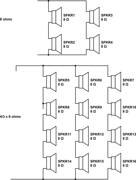
The scale factor for impedance of similar speakers x in series and y units in parallel noted as xSyP =. x/y.

So the ideal way is to arrange polarities and speakers assuming all are equal here; is have an equal number in Series as per number in Parallel.

Rev1 added info


Speaker DCR (ohms) readings are about 50% of the rated impedance or 4 ohms for an 8 ohm speaker.

  • Calibrate with leads shorted to use the result as 0 ohms.
    • If 8 x 8 ohm speakers were wired in parallel the result would be;
    • 4 ohm / 8 = 0.5 Ohms

schematic

simulate this circuit – Schematic created using CircuitLab

The speaker impedance is not critical but there are limits usually 4 ~ 16 ohm range. If Z is too high then power is limited by voltage, and if Z is too low then distortion rises with current and you risk blowing protection fuse or Amplifier from excess heat or current.

\$\endgroup\$
2
  • \$\begingroup\$ Thanks...for the interested reader more details can be found in electronics.stackexchange.com/questions/180853/…. Unfortunately this does not address the measurement issue raised by my question. \$\endgroup\$
    – Brian B
    Commented Dec 27, 2017 at 22:38
  • \$\begingroup\$ I'll add more examples. \$\endgroup\$
    – D.A.S.
    Commented Dec 28, 2017 at 0:45

Your Answer

By clicking “Post Your Answer”, you agree to our terms of service and acknowledge you have read our privacy policy.

Not the answer you're looking for? Browse other questions tagged or ask your own question.