1
\$\begingroup\$

I would like to power a white LED from batteries.

The LED I'd like to use has a forward voltage of 3.3V, the datasheet specifies the voltage range from minimum 2.8V to maximum 3.8V.

My idea is to use 1.5V AA or AAA batteries to power the LED, I don't want to use Lithium batteries for this project. I'm open to alternative suggestions though, if they would fit the project better. I'm aiming for a long battery life though, so no button cells.

If I use 2 batteries, I get 3V - this would be in the allowed range, but very close to the lower limit of 2.8V. As soon as both batteries drop to 1.4V, I'm out.

If I use 3 batteries, I get 4.5V and therefore a much greater voltage range that I can work with, but I have to get rid of something between 3 * 1.5 - 3.3 = 1.2V and 3 * 1.3 - 3.3 = 0.6 V.

I see several options here:

  • Just go with a fixed resistor and drop 1.2V. Works fine when the batteries are fully charged, LED will become dimmer over time until the batteries reach (2.8 + 1.2) / 3 = 1.33V

  • Use a buck converter to convert 4.5V to 3.3V. I'm not very experienced with buck converters and all items that my local electronics supplier has stocked that have a output voltage of 3.3V need at least 6V input voltage. I don't mind cramming more batteries in there, but does that give me any advantage?

    I guess that using a buck converter should give me a steady supply of 3.3V as long as the converter has any input voltage above a certain treshold, so I'd not experience any LED dimming. Is that correct?

  • Use a linear regulator. Researching my question I found some answers that said something like "a linear regulator is fine, because you don't have much voltage to drop". Usually those questions where about micro controllers though and had a power consumption of some hundred µA. Would using a linear regulator work with a LED that has a power consumption of 20 or 30 mA?

Can you give me some advice which solution I should follow or am I going in the totally wrong direction? Would those solutions still work if I would want to power two or three LEDs with identical specifications?

\$\endgroup\$
4
  • 3
    \$\begingroup\$ Are you familiar with a circuit called the Joule Thief? It's a simple boost converter. A side effect of boost converters is they can drag every last joule out of a dying battery. Another side effect is they can regulate output current precisely, which you need if you are driving a white LED for illumination. \$\endgroup\$ Commented Dec 28, 2017 at 23:06
  • \$\begingroup\$ No, until now I've only ever powered LEDs from micro controller outputs or similar, so I always had a fixed voltage to work with. Going to look into that right away :) \$\endgroup\$
    – m00dy
    Commented Dec 28, 2017 at 23:12
  • 1
    \$\begingroup\$ electronics.stackexchange.com/a/341293/139766 \$\endgroup\$
    – Trevor_G
    Commented Dec 28, 2017 at 23:42
  • \$\begingroup\$ ti.com/lit/ds/symlink/lm2750.pdf \$\endgroup\$
    – Trevor_G
    Commented Dec 28, 2017 at 23:46

2 Answers 2

6
\$\begingroup\$

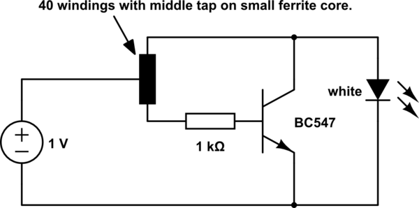
Try this little circuit for a start. It runs from near-empty AAA batteries.

schematic

simulate this circuit – Schematic created using CircuitLab

Well, how does it work?

  1. In the beginning, both the transistor and the LED are shut off.
  2. A small current flows through the lower leg of the coil into the base of the transistor.
  3. The transistor turns on the C-E path. Now a much higher current flows through the upper leg of the coil and the collector of the transistor.
  4. Because the upper and lower leg of the coil are magnetically coupled, the current cannot flow in opposite directions in both legs. The small current into the transistor base runs dry.
  5. The transistor shuts off again.
  6. The current running through the coil cannot be shut off in an instant! That's why the coil increases the voltage at its terminals to sustain the current. That voltage is added on top of the source voltage.
  7. Eventually, the voltage is high enough to bring the LED into conduction (and lighting it up in the process.)
  8. The voltage of the coil decreases again.
  9. The LED shuts off again and the process restarts.

Congrats. You have built and understood the simplest boost converter of all.

\$\endgroup\$
2
  • \$\begingroup\$ Sorry, I'm not a native speaker. What do you mean by "middle tap"? \$\endgroup\$
    – m00dy
    Commented Dec 29, 2017 at 11:16
  • \$\begingroup\$ Me neither. After 20 tight turns, leave one turn loose, then do another 19 tight turns. That loose turn is your middle/center tap. Connect it to the plus contact of the battery. \$\endgroup\$
    – Janka
    Commented Dec 29, 2017 at 12:41
0
\$\begingroup\$

In order to achieve the efficiency of existing cheap torchlights designed for Alkaline or better ones for Lithium Polymer, the current regulation must be done at 5% or less of the voltage available for efficiency reasons. This implies a very low shunt resistance and current sense boost to regulate the PWM duty cycle.

For power spec; I assume the minimum LED power is 1W and can be up to 10W with suitable cell power to match and for density reasons LiPo is greatly preferred although for cheapest torches, alkaline is used but you may find "batteries not included".

Here is a 10W reference design using 0.05Ω current sense and Push-Pull half bridge with continuous conduction mode choke. PWM Regulation done by PIC uC.

https://www.microchip.com/promo/hp-led-flashlight

\$\endgroup\$

Your Answer

By clicking “Post Your Answer”, you agree to our terms of service and acknowledge you have read our privacy policy.

Not the answer you're looking for? Browse other questions tagged or ask your own question.