3
\$\begingroup\$

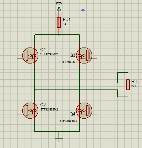
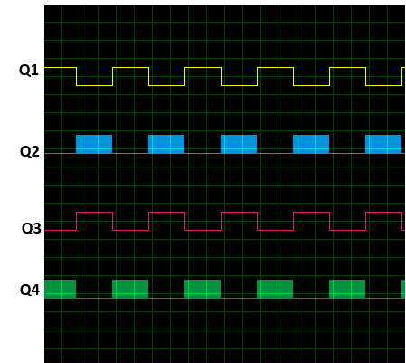
As a part of my effort to build a pure sine inverter I made the following MOSFET H Bridge. This was connected to a load through a LC filter where PWM signals are given as in the diagram below.PWM frequency is 16kHz with Q1 & Q3 switching at 50Hz.

PWM signals for Q1,Q2,Q3,Q4

While testing after working for few minutes the fuse blew, Q1 and Q2 failed short circuiting Drain & Source.

For debugging I removed the Filter, connected a resistive load directly and reduced the supply voltage to 170V.

Circuit after modifying

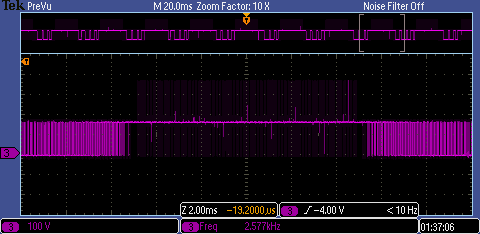
I checked the gate signals of individual MOSFETs. which seems fine. However I got the following waveform for Vds of Q2. There are few spikes reaching up to 380V when supply voltage is 170V. I guess that a supply voltage of 325V these spikes will be much larger damaging the MOSFETs.

enter image description here

What is the reason for these spikes?

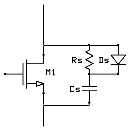
Can they be minimized by a RC snubber?

If so how can i calculate values for R & C ?

Any help is much appreciated. Thanks in advance.

Update

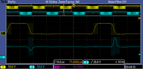
Further zooming in i found that the spikes occur when the opposite MOSFET is turned on. Following is the Vds of Q2(Yellow) and Vds of Q4(Cyan). I further reduced supply voltage to 90V.

enter image description here

\$\endgroup\$
4
  • 1
    \$\begingroup\$ Not related to the spikes - do you have a disoverlap mechanism in place? \$\endgroup\$ Commented Dec 30, 2017 at 16:06
  • \$\begingroup\$ You can minimize the inductance by the area of the loop current being switched with paired wires. V=LdI/dt then apply 100R+10nF cap in series \$\endgroup\$
    – D.A.S.
    Commented Dec 30, 2017 at 18:45
  • \$\begingroup\$ @VladimirCravero No. But I have added a considerable dead time, and haven't observed any overlap in switching signals yet. \$\endgroup\$
    – Chinthaka
    Commented Dec 31, 2017 at 7:33
  • \$\begingroup\$ @TonyStewart.EEsince'75 Sorry,I didn't follow you. \$\endgroup\$
    – Chinthaka
    Commented Dec 31, 2017 at 7:34

3 Answers 3

5
\$\begingroup\$

There are three main causes for what you are seeing, which one or combination is dependant on specifics of your setup

Probe pickup

There is the possibility these spikes are not real & are artefacts of how you are probing. If you are using a x10 or x100 probe then the clip is EARTH referenced. If you are connecting this to the SOURCE of the lower FET this will not be the same EARTH as the scope & thus there will be some bounce.

Not the same EARTH? but the circuit indicates the SOURCE of Q2, Q4 are EARTH. In practice they are not simply due to stray inductance - not all earths are equal.

It could pickup due to a loop you created at the point of measurement.

Poor powercore layout

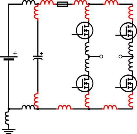
Below is what you believe your layout is ( I have added the DCLink capacitor because I really hope you have one...)

enter image description here

In practice it is slightly different

enter image description here

In physically constructing your H-Bridge you may have chosen convenience in placement of suitability of flow. The stray inductance in RED are some that will compound switching overshoots as you force commutate the current.

Gatedrive and device specifics

Depending on specifics of your gate-drive you maybe driving the MOSFETs too hard (gate resistor too low), the layout is poor such that the driver can't keep the device off.

Voltage overshoot is an expected byproduct of forced-commutation

Finally... there will always be some voltage overshoot because the existence of stray inductance like there will always be reverse recovery current. Improvements in layout can improve this, slowing down switching times can equally improve it or if it really cannot be reduced... snubber circuitry can be added to dissipate the additional energy

enter image description here

As to why you lost control...

While testing after working for few minutes the fuse blew, Q1 and Q2 failed short circuiting Drain & Source.

That may or may not be related to the observed overshoots BUT aspects of your control could also contribute: deadtime, minimum pulsewidth etc.

\$\endgroup\$
4
  • \$\begingroup\$ I used an differential probe & kept those connections as short as possible. So can there still be probe pickup?I do have DC link Caps. I'm using isolated power supply modules to switch the MOSFETs via TLP250 opto-couplers. What you mean by driving a MOSFET too hard is unclear to me. \$\endgroup\$
    – Chinthaka
    Commented Dec 31, 2017 at 7:50
  • \$\begingroup\$ I also thought about adding a snubber. But my calculations were way off. Can you explain how i can calculate these values. All i have found online is related to minimizing ringing. Thank you for helping me out. \$\endgroup\$
    – Chinthaka
    Commented Dec 31, 2017 at 7:52
  • \$\begingroup\$ Overshoot is just ringing. Essencially are wanting to move a volt-second overshoot from the switching device to the RC snubber. \$\endgroup\$
    – user16222
    Commented Jan 2, 2018 at 12:23
  • \$\begingroup\$ Hi JonRB As I have updated, when Q2 is switching,its wave forms are almost perfect, the spikes appear across Q4 which is in OFF state for the whole period. I thinks it is due to stray inductance you mentioned. but can i still use an RC snubber for this? \$\endgroup\$
    – Chinthaka
    Commented Jan 2, 2018 at 13:19
0
\$\begingroup\$

I would place a decoupling capacitor after the fuse as some fuses can have a high inductance. I would also place fast acting schottky diodes across the fets to protect them.

\$\endgroup\$
3
  • \$\begingroup\$ schottky diodes? MOSFETs do have body diodes. Should i add more externalY? \$\endgroup\$
    – Chinthaka
    Commented Dec 31, 2017 at 7:54
  • \$\begingroup\$ Yes you should add more externaly. the reason is that the body diode of most mosfets is not a very good diode. if you know you have transients that should be clamped to supply it is better to used external diodes across the fets. \$\endgroup\$
    – user173292
    Commented Dec 31, 2017 at 12:12
  • \$\begingroup\$ The schottky are also faster, and help also in spreading the zones were power is dissipated. \$\endgroup\$ Commented Dec 31, 2017 at 13:50
0
\$\begingroup\$

The answer was simple, But it took 6 burnt out mosfets to find out. The problem was with the bulk capacitor. It was initially placed a bit too far from the H bridge. Moving it close,right next to the bridge and the filter capacitor seems to solve the issue. Thanks everyone for your contribution.

\$\endgroup\$

Your Answer

By clicking “Post Your Answer”, you agree to our terms of service and acknowledge you have read our privacy policy.

Not the answer you're looking for? Browse other questions tagged or ask your own question.