0
\$\begingroup\$

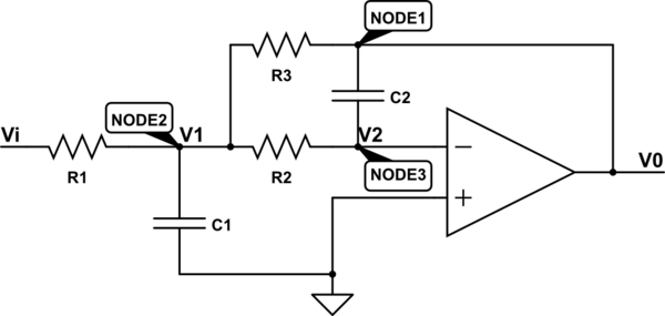
Can someone please help me find the transfer function of this circuit.

$$ \frac{V_0(s)}{V_i(s)}= \dots $$

schematic

simulate this circuit – Schematic created using CircuitLab

This is what I have done so far. $$ I_{R1}+I_{R3}=I_{R2}+I_{C1} $$ $$ I_{R2}+I_{C2}=0 $$ $$ I_{R3}=I_{C2} $$ By substituting currents I reach the following formula. $$ \frac{V_i-V_1}{R_1}+2 \cdot S \cdot V_0 \cdot C_2 = S \cdot V_1 \cdot C_1 $$

\$\endgroup\$
6
  • 3
    \$\begingroup\$ Show us what you've done, like node voltage method. \$\endgroup\$
    – τεκ
    Commented Jan 9, 2018 at 18:41
  • 1
    \$\begingroup\$ Please show us your attempted solution, and go into more detail on what has you stuck. \$\endgroup\$
    – Daniel
    Commented Jan 9, 2018 at 18:42
  • 1
    \$\begingroup\$ @τεκ I updated the post and added what I have done so far \$\endgroup\$ Commented Jan 9, 2018 at 19:05
  • \$\begingroup\$ You have made a mistake - the output current of the amplifier is not zero, so \$I_{R3} \neq I_{C2}\$ \$\endgroup\$
    – τεκ
    Commented Jan 9, 2018 at 19:22
  • \$\begingroup\$ Thanks @τεκ, but how can I write the output current \$I_{out}=?\$ and also how can I eliminate the \$V_1\$ ? \$\endgroup\$ Commented Jan 9, 2018 at 19:28

2 Answers 2

2
\$\begingroup\$

There are many options to determine the transfer function of such a filter. One of them is to use the fast analytical circuit techniques or FACTs. By doing so, you will determine the time constants associated with each of the energy-storing elements of your filter. Because there are two capacitors with independent state variables, this is a second-order system whose denominator obeys the following expression: \$D(s)=1+b_1s+b_2s^2\$. What is cool with the FACTs is that you will independently determine \$b_1\$ and \$b_2\$ through individual sketches leading to a canonical form without much efforts. We can start the analysis for the \$s=0\$: open the capacitors and solve the transfer function \$H_0\$. By inspection, you have \$H_0=-\frac{R_3}{R_1}\$. The equivalent sketch is
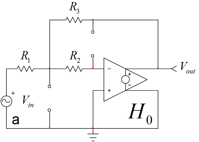
enter image description here

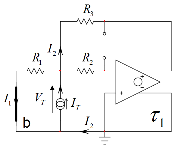
Then, you reduce \$V_{in}\$ to 0 V and you determine the resistance by "looking" into \$C_1\$'s terminals while \$C_2\$ is in its dc state (open-circuited). The sketch is below:
enter image description here

If you do the simple maths ok around this circuit, as confirmed by the below simulation, the resistance is 0 and the time constant \$\tau_1\$ is equal to 0.
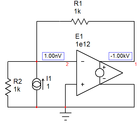
enter image description here

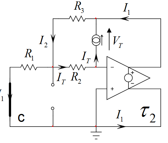
For the second time constant, we now "look" at the resistance offered between \$C_2\$'s terminals as illustrated below (\$C_1\$ is set in its dc state):
enter image description here

If you do the maths ok and consider a perfect op amp, the second time constant \$\tau_2\$ is equal to \$\tau_2=C_2(R_2+R_3+\frac{R_2R_3}{R_1})\$. According to the definition, \$b_1=\tau_1+\tau_2=C_2(R_2+R_3+\frac{R_2R_3}{R_1})\$.

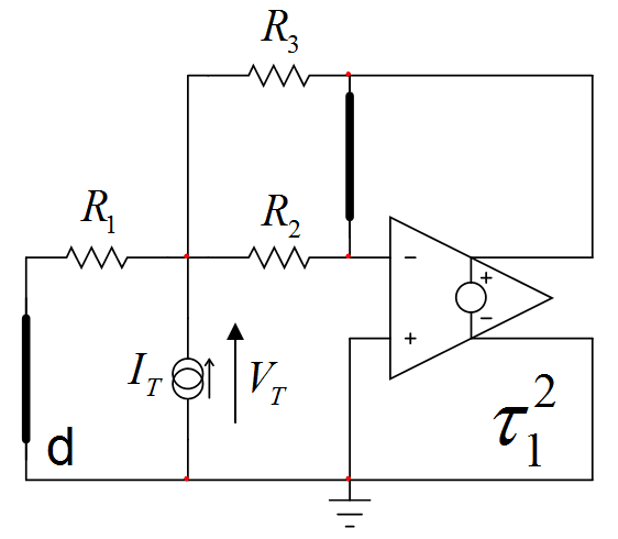
To obtain \$b_2\$, we will now determine the time constant involving \$C_1\$ while \$C_2\$ is a short circuit:
enter image description here

Doing the maths (look at the virtual ground at the (-) pin) leads to \$\tau_{21}=C_1(R_1||R_2||R_3)\$ and this is it, we have \$b_2=\tau_2\tau_{21}=C_2(R_2+R_3+\frac{R_2R_3}{R_1})C_1(R_1||R_2||R_3)\$. The complete transfer function is thus:

\$H(s)=-\frac{R_3}{R_1}\frac{1}{1+sC_2(R_2+R_3+\frac{R_2R_3}{R_1})+s^2C_2(R_2+R_3+\frac{R_2R_3}{R_1})C_1(R_1||R_2||R_3)}=H_0\frac{1}{1+\frac{s}{Q\omega_0}+(\frac{s}{\omega_0})^2}\$

The FACTs let you determine the transfer function through a succession of simple sketches that you can individually solve and check with a simple simulator. Should you make a mistake, identify the guilty sketch and correct it: no need to restart from scratch as with classical analysis. Also, as you can see, the result is already factored without the need to inject further energy into the factoring of an arm-long expression mixing all the terms (brute-force analysis). This filter is part of the many solved problems described here.
\$\endgroup\$
5
  • \$\begingroup\$ Just a question about the last step (obtaining b2): why did you choose to keep C1 in circuit and short C2? Why not to keep C2 in the circuit and short C1? \$\endgroup\$ Commented Jan 19, 2018 at 14:38
  • \$\begingroup\$ Yes, you can swap as you suggested but, in this case, you would use the first time constant: \$\tau_1\tau_{12}=\tau_2\tau_{21}\$. This redundancy helps you pick the simplest combination of time constants (the simplest result) but it also helps when there is an indeterminacy. Please have a look at the tutorial:cbasso.pagesperso-orange.fr/Downloads/PPTs/… \$\endgroup\$ Commented Jan 19, 2018 at 16:51
  • \$\begingroup\$ \$\tau_1=0\$ in your calculations, so \$\tau_1\tau_{12}=0\$. But \$\tau_2\tau_{21}\$ is not zero, so there is no equality. \$\endgroup\$ Commented Jan 19, 2018 at 18:46
  • 1
    \$\begingroup\$ No, if you calculate \$\tau_{12}\$, you will see that it approaches infinity so if you multiply it by \$\tau_1\$ which is zero, you have an indeterminacy. That is the reason why you use the second expression. For the sake of the experiment, if you now fix \$A_{OL}\$ to a finite value and you simulate both time constants \$\tau_1\tau_{12}\$ and \$\tau_2\tau_{21}\$, the redundancy holds perfectly. \$\endgroup\$ Commented Jan 19, 2018 at 19:16
  • \$\begingroup\$ Yes, I see it now. You are right. \$\endgroup\$ Commented Jan 19, 2018 at 22:59
1
\$\begingroup\$

Using the nodes method (KCL) $$ I_{R1}+I_{R3}=I_{R2}+I_{C1} $$ $$ I_{R2}+I_{C2}=0 $$

then, $$ \frac{V_i-V_1}{R_1}+\frac{V_0-V_1}{R_3}=V_1 \cdot C_1 \cdot S + \frac{V_1}{R_2} $$ $$ V_1=-R_2 \cdot C_2 \cdot V_0 \cdot S $$

Now Vo can be found by Cramer’s Rule

$$ \frac{V_0}{V_i}= - \frac{\frac{1}{R_1R_2C_1C_2}}{S^2 + \left( \frac{1}{R_1C_1} + \frac{1}{R_2C_1} + \frac{1}{R_3C_1} \right) S + \frac{1}{R_2R_3C_1C_2} } $$

\$\endgroup\$
2
  • \$\begingroup\$ Yes, this solution is correct but you are missing a - sign as this is an inverting structure. Also, you should rewrite it to fit the 2nd-order canonical form as \$-\frac{1}{1+s(\frac{1}{R_1C_1}+\frac{1}{R_2C_1}+\frac{1}{R_3C_1})R_1R_2C_1C_2+s^2R_1R_2C_1C_2}\$ but then, you need to factor-in a leading term which the dc gain for \$s=0\$. See what I obtained with the fast analytical techniques. Please use a lowercase \$s\$ in your expressions. Good job! : ) \$\endgroup\$ Commented Jan 9, 2018 at 20:38
  • \$\begingroup\$ Thank you @VerbalKint for your advice ! I'll keep it in mind. My professor usually use the canonical form as \$D(s)= s^2 + 2 \xi \omega_n s + \omega_n^2 \$ \$\endgroup\$ Commented Jan 9, 2018 at 21:24

Your Answer

By clicking “Post Your Answer”, you agree to our terms of service and acknowledge you have read our privacy policy.

Not the answer you're looking for? Browse other questions tagged or ask your own question.