4
\$\begingroup\$

So my current project is building a replica of the ARP Pro Soloist synthesizer from the 70’s. The project is mostly going very smoothly, but I am having some issues with the power supply section of the synth: Even after many searches, I don’t know what kind of power transformer to select.

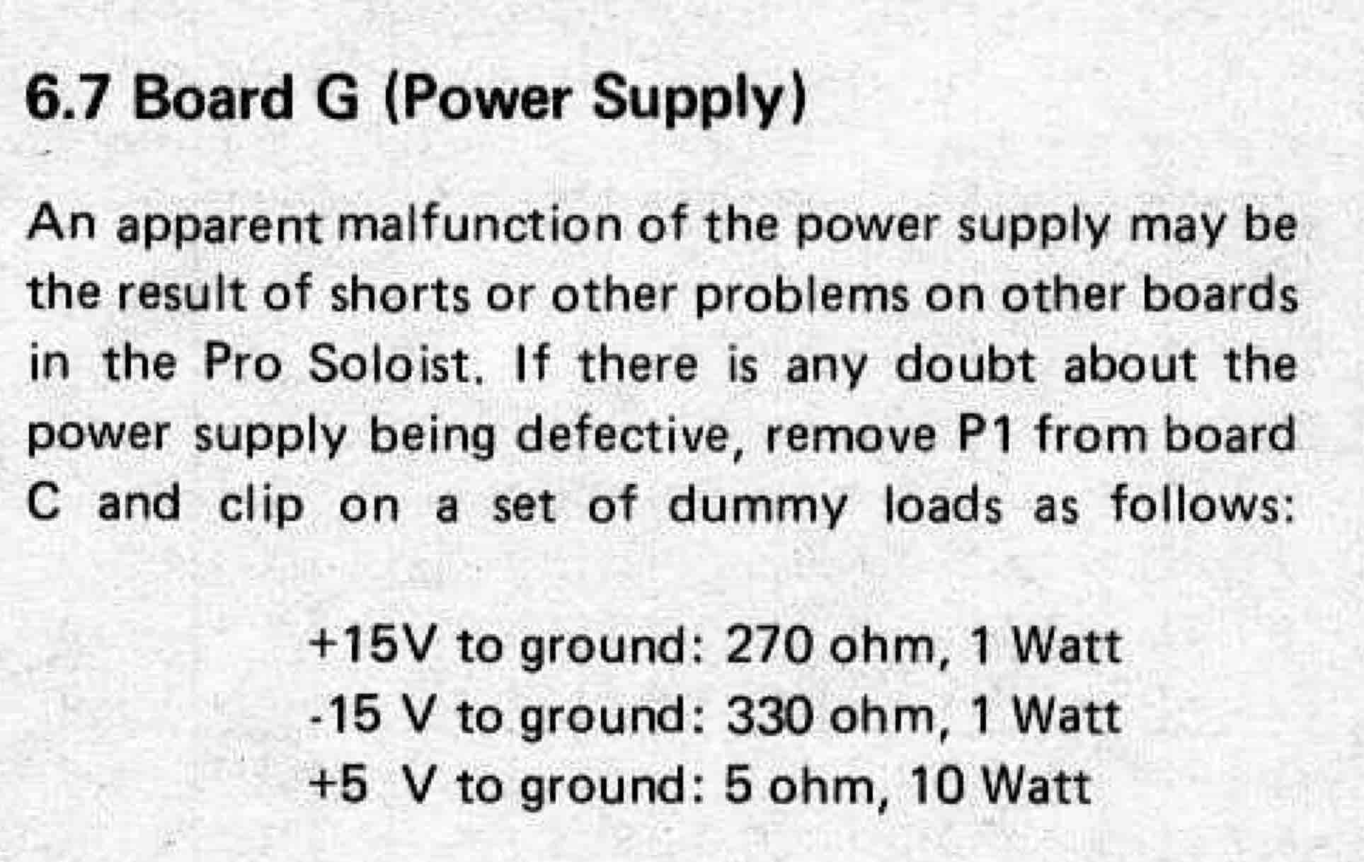
enter image description here

As you can see on the schematic, the original unit used a transformer with a center tapped primary and two center tapped secondaries. This seems unusual to me, because most transformers I can find have either only one center tapped secondary winding, or two secondaries, but not center tapped. Other than that, there are almost no other indicators of what kind of transformer was used. The only other things that caught my attention are that the power supply uses a 250 mA fuse, which means - if I understand it correctly - that the instrument doesn’t use more than 250 mA of total current, because the fuse would blow otherwise. Also, the 1N4448 diodes used here as a bridge rectifier have an average forward current IF(AV) of only 150 mA.

The power supply outputs 3 individual power rails of + 5 V, + 15 V, and - 15 V, so the transformer must be able to handle that.

enter image description here

Another thing that may help you to help me is something I found in the service manual for the instrument. The section about the power supply mentions what kind of dummy loads should be used to test the power supply. Using Ohm’s law to calculate the current for each rail, I got the following results:

  • + 5 V = 1 A
  • + 15 V ≈ 0.06 A = 60 mA
  • - 15 V ≈ 0.05 A = 50 mA

One final thing to mention is that I would like to use a toroidal transformer, since they are less noisy and better suited for audio applications like this one.

So my questions are:

  • What kind of power transformer should I use?
  • How can I know the voltage ratings for each of the secondary windings? Aren’t they supposed to be a little bit higher than the needed voltage?
  • What current rating is the transformer supposed to have?
  • And most importantly: Where can I buy it?

I really appreciate any help!

Thank you in advance, Martin

\$\endgroup\$
1
  • 3
    \$\begingroup\$ Unless you're looking for extreme component-by-component authenticity, you should consider simply purchasing modern complete power supply modules to supply the +5V and +/-15V to the rest of the project. \$\endgroup\$
    – Dave Tweed
    Commented Jan 14, 2018 at 14:07

2 Answers 2

4
\$\begingroup\$

The transformer primary centre-tap is for 115 / 230 V operation. If you don't need it you can just choose the voltage for your region.

The transformer may have been custom wound and you could have difficulty finding a match from any of the large suppliers although +5 V and +/-15 V are common requirements. You can of course use two separate transformers - one for the 5 V supply and one for the +/-15 V supply. Parallel the tranformer primaries to the fused mains supply and connect the common ground points after the rectifier.

If you need to create your own supplies the 7805 (1 A) and 78L15 / 79L15 (0.5 A) voltage regulators would suffice. There are plenty of designs and tutorials on these devices on the web. Pay attention to decoupling capacitors.

Since +5 V and +/-15 V are so common you could also just purchase readymade PSUs. Look out for low noise power supplies so that you don't get audio interference.

\$\endgroup\$
5
  • \$\begingroup\$ Hello Transistor! Thank you for your quick reply! I have also thought about the "two transformers in parallel method", but I wanted to ask the question here first so see whether there's a better option. So basically what I need is something a 18V-0V-18V/2x18V/36V in series (depends on how it is marked) 150mA transformer, and a 9V-0V-9V/2x9V/18V in series 1A transformer? And what do you mean by "connect the common ground points after the rectifier"? You probably mean the two center taps of the two transformers, but how can they be connected after the two rectifiers? \$\endgroup\$ Commented Jan 14, 2018 at 15:25
  • \$\begingroup\$ Those voltages look too high. Transformer output is given in \$ V_{RMS} \$ so the peak voltage will be \$ \sqrt 2 \$ times that. For 15 V DC a 15 V AC transformer would peak at \$ 15 \sqrt 2 \ \mathrm V\$. Even with your diode voltage drop and some ripple that still should give you enough headroom. Again check for published designs. The point about the GNDs is that you might have a single secondary and full-wave rectifier for your 5 V supply. In this case you need to make sure you don't short out your rectifier by grounding one leg of the transformer. \$\endgroup\$
    – Transistor
    Commented Jan 14, 2018 at 17:21
  • \$\begingroup\$ I am not sure if I understand why the voltages are too high. If we assume that I will use two independent transformers, then we can look at the two transformers as two different power supplies. One of them is dual and outputs + 15 V and - 15 V. The other one outputs only + 5 V. The dual power supply a needs a transformer with at least 30 VPP so that both rails get at least 15 VP. I now plan using the Triad FS36-170 transformer, because it will output 36 VPP, so there will be enough headroom for the losses after rectification and regulation. I found some other designs that use similar values. \$\endgroup\$ Commented Jan 14, 2018 at 19:12
  • \$\begingroup\$ For the + 5 V supply I now plan using the Triad FS10-1200 (I found those transformers today), because it outputs 10 VPP at 1.2 A, but since it's not a dual supply there will be 5 V headroom, which also seems fine considering the diode and regulation losses... Am I misunderstanding something? \$\endgroup\$ Commented Jan 14, 2018 at 19:14
  • \$\begingroup\$ There's a good explanation here: electrosome.com/power-supply-design-5v-7805-voltage-regulator. You might also find some designs and calculations in the datasheets. \$\endgroup\$
    – Transistor
    Commented Jan 14, 2018 at 19:34
2
\$\begingroup\$

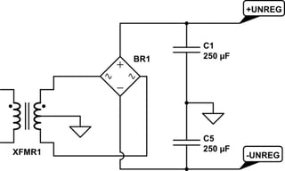
Your upper power supply's unregulated circuit looks something like this:
schematic

simulate this circuit – Schematic created using CircuitLab

It's a very standard approach. The unregulated output will have some ripple on it. The exact amount depends on a lot of factors. But you have to expect some. We'll come back to that in a moment.

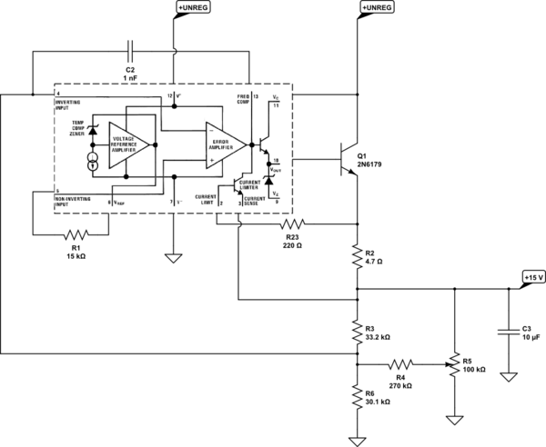
Here is the power supply circuit (LM732C, I believe) for the \$+15\:\text{V}\$ power supply:
schematic

simulate this circuit

\$R_5\$ allows adjustment. (Not shown, but pretty obvious from the schematic is the fact that the \$-15\:\text{V}\$ supply regulation comes from an added circuit that references this one using a long-tailed pair diff-amp and another potentiometer.)

You can readily see that the internal output BJT (shown between pins 10 and 11) is supplemented with \$Q_1\$, forming a Darlington output pair. \$R_2\$ is used for current limiting and will require perhaps \$800\:\text{mV}\$ (just using rough numbers; no need to get too worked up over minor variations.) This means that the emitter of \$Q_1\$ will be at worst about \$15.8\:\text{V}\$. You need at least two more \$V_{BE}\$ junctions above that for the output of the internal error amplifier, but it also will need some headroom.

Looking at the datasheet it appears that, discounting \$Q_1\$'s needs for a moment, there is at worst another \$3\:\text{V}\$ required above the base of \$Q_1\$. If you plan for that, then the unregulated supply's minimum voltage needs to be about (with one \$V_{BE}\$ for \$Q_1\$ and one \$V_{BE}\$ for current limiting) \$2\cdot 800\:\text{mV}+3\:\text{V}=4.6\:\text{V}\$ above the desired \$+15\:\text{V}\$.

For the unregulated voltage ripple, I have to guess a little. But if I estimate the current limit at about \$\frac{800\:\text{mV}}{4.7\:\Omega}\approx 170\:\text{mA}\$ then I find about \$\frac{\text{d}V}{\text{d}t}=\frac{170\:\text{mA}}{250\:\mu\text{F}}\approx 680\:\frac{\text{V}}{\text{s}}\$. Roughly speaking for a \$60\:\text{Hz}\$ system, this suggests about \$5\:\text{V}\$ of ripple.

So I'd probably add another \$5\:\text{V}\$ to reach the unloaded estimate for the transformer. Therefore, I think around \$15\:\text{V}+4.6\:\text{V}+5\:\text{V}=24.6\:\text{V}\$, unloaded, as a very rough guess, after the bridge has had its bite. Adding in the bridge, I'd go for \$26\:\text{V}\$. Since this is a bipolar supply, that doubles. So now we are at \$52\:\text{V}\$. Turning that into RMS, I get about \$36-37\:\text{V}_\text{RMS}\:\text{CT}\$. I would want windings capable of perhaps \$250\:\text{mA}_\text{RMS}\$, so a rating of about \$9-10\:\text{VA}\$.

Should be between US$10 and US$15, or so.

It's not critical. The main thing you need to be sure of is that you have at least enough headroom, taking into account unregulated ripple, LM723C overhead, external BJT overhead, and current limit overheads to get to the required voltage there. Again, I haven't considered changes that might be indicated by the negative rail circuit. (I'm assuming it's no worse.) And I've ignored the other winding needed for the \$5\:\text{V}\$ supply.


That's just the one transformer. You probably need to consider getting two, instead of a single one wound perfectly for your use. You might get lucky. But if you can consider it, accept the use of two. Otherwise, you may be looking seriously for a long search.

For the \$5\:\text{V}\$ supply, I get about a DC rating of \$2\:\text{A}\$. Looking at their output capacitor, I again get a voltage ripple of as much as \$5\:\text{V}\$. Plus perhaps another \$3\:\text{V}\$ of overhead for the simple circuit, rectifying diodes, and its current limit feature. Again, this has the half-winding (CT) voltage requiring a minimum of \$13\:\text{V}\$, which again is only half the winding. So I'd be looking for something around \$18\:\text{V}_\text{RMS}\:\text{CT}\$ and rated at about \$40\:\text{VA}\$.


I hate to suggest something specific, but if you are looking to get both in a single transformer, this might work: Bel Signal Transformer 36-2 at Mouser.com. See the datasheet at Bel Signal Transformer 36-2 Datasheet. If you went with two transformers, it would be cheaper to get. But at least this gives you an idea.

\$\endgroup\$
7
  • \$\begingroup\$ Hello jonk! Thank you for you very quick and thorough reply! I also really appreciate that you redrew the schematic and did all the calculations for me! So considering all your suggestions, I ended up looking at the Triad FS36-350 and FS16-2250 transformers. The former one delivers 36 V CT and is rated for 12 VA, so it's a little bit higher that you suggested, but it should work. The latter one is a 16 V CT transformer and is rated for 36 VA, so it's a little bit lower than you suggested, but again, I think it should work. They are both small and available at Mouser, so they seem perfect! \$\endgroup\$ Commented Jan 14, 2018 at 23:18
  • \$\begingroup\$ @Martin The first one seems fine. The second one might be a worry, might not. 16 V CT might be a bit low. But you won't know for sure until you try, I suppose. You can always replace it, later. \$\endgroup\$
    – jonk
    Commented Jan 14, 2018 at 23:26
  • \$\begingroup\$ Then other options are the VPP36-280 and the VPP20-2800, which are 36 V CT rated 10 VA, and 20 V CT rated 56 VA respectively. The latter one is rated quite a bit higher than you suggested. They are not as small as the ones I found earlier, but they might be the needed answer. \$\endgroup\$ Commented Jan 15, 2018 at 0:07
  • \$\begingroup\$ @Martin For the transformers, bigger is often better. But I've already added margins for the voltage magnitudes, too be safer. But this comes at a possible unnecessary cost -- heat. Increasing the voltages further can work, as it is even more margin. But the downside is that some bjts will be dissipating even more. Just be aware of the possibility and check things out when operating, later. \$\endgroup\$
    – jonk
    Commented Jan 15, 2018 at 0:12
  • \$\begingroup\$ Thank you very much for your help, jonk! I will consider all these things and try my best to find a fitting transformer! \$\endgroup\$ Commented Jan 15, 2018 at 1:30

Your Answer

By clicking “Post Your Answer”, you agree to our terms of service and acknowledge you have read our privacy policy.

Not the answer you're looking for? Browse other questions tagged or ask your own question.