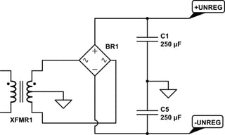
Your upper power supply's unregulated circuit looks something like this:

simulate this circuit – Schematic created using CircuitLab
It's a very standard approach. The unregulated output will have some ripple on it. The exact amount depends on a lot of factors. But you have to expect some. We'll come back to that in a moment.
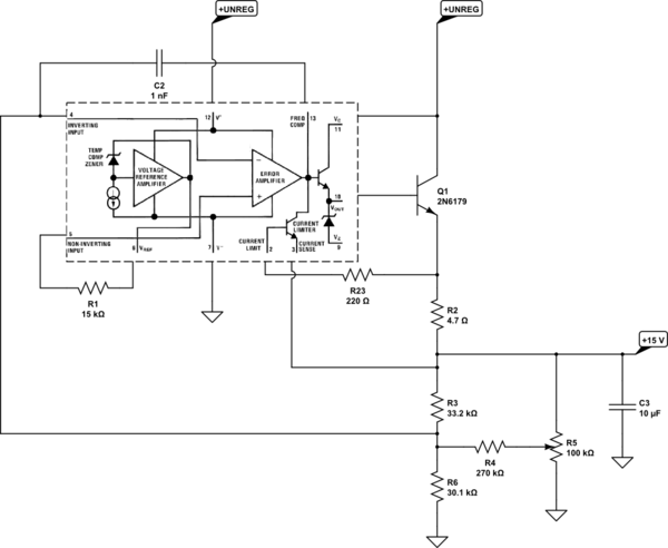
Here is the power supply circuit (LM732C, I believe) for the \$+15\:\text{V}\$ power supply:

simulate this circuit
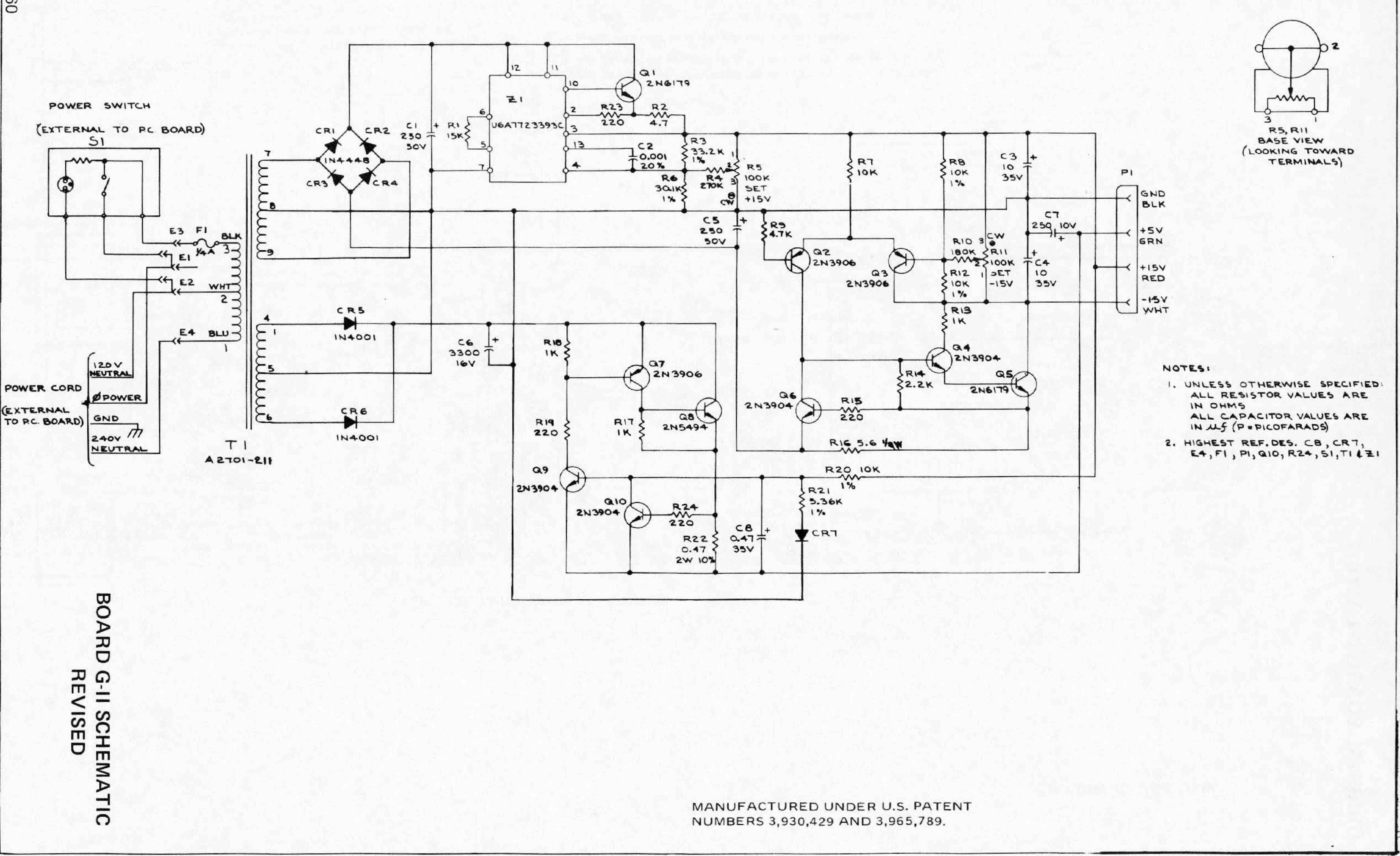
\$R_5\$ allows adjustment. (Not shown, but pretty obvious from the schematic is the fact that the \$-15\:\text{V}\$ supply regulation comes from an added circuit that references this one using a long-tailed pair diff-amp and another potentiometer.)
You can readily see that the internal output BJT (shown between pins 10 and 11) is supplemented with \$Q_1\$, forming a Darlington output pair. \$R_2\$ is used for current limiting and will require perhaps \$800\:\text{mV}\$ (just using rough numbers; no need to get too worked up over minor variations.) This means that the emitter of \$Q_1\$ will be at worst about \$15.8\:\text{V}\$. You need at least two more \$V_{BE}\$ junctions above that for the output of the internal error amplifier, but it also will need some headroom.
Looking at the datasheet it appears that, discounting \$Q_1\$'s needs for a moment, there is at worst another \$3\:\text{V}\$ required above the base of \$Q_1\$. If you plan for that, then the unregulated supply's minimum voltage needs to be about (with one \$V_{BE}\$ for \$Q_1\$ and one \$V_{BE}\$ for current limiting) \$2\cdot 800\:\text{mV}+3\:\text{V}=4.6\:\text{V}\$ above the desired \$+15\:\text{V}\$.
For the unregulated voltage ripple, I have to guess a little. But if I estimate the current limit at about \$\frac{800\:\text{mV}}{4.7\:\Omega}\approx 170\:\text{mA}\$ then I find about \$\frac{\text{d}V}{\text{d}t}=\frac{170\:\text{mA}}{250\:\mu\text{F}}\approx 680\:\frac{\text{V}}{\text{s}}\$. Roughly speaking for a \$60\:\text{Hz}\$ system, this suggests about \$5\:\text{V}\$ of ripple.
So I'd probably add another \$5\:\text{V}\$ to reach the unloaded estimate for the transformer. Therefore, I think around \$15\:\text{V}+4.6\:\text{V}+5\:\text{V}=24.6\:\text{V}\$, unloaded, as a very rough guess, after the bridge has had its bite. Adding in the bridge, I'd go for \$26\:\text{V}\$. Since this is a bipolar supply, that doubles. So now we are at \$52\:\text{V}\$. Turning that into RMS, I get about \$36-37\:\text{V}_\text{RMS}\:\text{CT}\$. I would want windings capable of perhaps \$250\:\text{mA}_\text{RMS}\$, so a rating of about \$9-10\:\text{VA}\$.
Should be between US$10 and US$15, or so.
It's not critical. The main thing you need to be sure of is that you have at least enough headroom, taking into account unregulated ripple, LM723C overhead, external BJT overhead, and current limit overheads to get to the required voltage there. Again, I haven't considered changes that might be indicated by the negative rail circuit. (I'm assuming it's no worse.) And I've ignored the other winding needed for the \$5\:\text{V}\$ supply.
That's just the one transformer. You probably need to consider getting two, instead of a single one wound perfectly for your use. You might get lucky. But if you can consider it, accept the use of two. Otherwise, you may be looking seriously for a long search.
For the \$5\:\text{V}\$ supply, I get about a DC rating of \$2\:\text{A}\$. Looking at their output capacitor, I again get a voltage ripple of as much as \$5\:\text{V}\$. Plus perhaps another \$3\:\text{V}\$ of overhead for the simple circuit, rectifying diodes, and its current limit feature. Again, this has the half-winding (CT) voltage requiring a minimum of \$13\:\text{V}\$, which again is only half the winding. So I'd be looking for something around \$18\:\text{V}_\text{RMS}\:\text{CT}\$ and rated at about \$40\:\text{VA}\$.
I hate to suggest something specific, but if you are looking to get both in a single transformer, this might work: Bel Signal Transformer 36-2 at Mouser.com. See the datasheet at Bel Signal Transformer 36-2 Datasheet. If you went with two transformers, it would be cheaper to get. But at least this gives you an idea.


