6
\$\begingroup\$

I'm very new to electronics and I built this guitar amp circuit on a breadboard:

enter image description here

and it was working really nicely. Now I've decided to put the circuit on a universal PCB which I'll use in the actual amp. I soldered all the components on but no sound comes out when I play. Because of the different layout of the universal PCB, the circuit's grounds are connected differently than they were on the breadboard, so maybe that's the potential problem since its the only difference I think there is. Sadly I don't remember what it looked like on the breadboard and I didn't take any pics. Heres the layout of the circuit on the universal PCB:

enter image description here

Heres something I don't understand, when I measure the potential between the output and the ground with a voltmeter, it corresponds nicely to the signal from the guitar, it seems like it should work. But when I measure the potential between the wires going into the speaker (which are connected to the output and the ground) I get zero volts between them always. Why is that and how can it be fixed?

Also sometimes when I poke around with the voltmeter at different spots on the ground and output it will randomly start working and sound will come out. I can't really notice any pattern when doing so though.

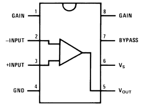
Heres the pin layout for the LM386 operational amplifier:

enter image description here

Once again I'm very new so I'm sure I'm making a ton of embarrassing mistakes and that my soldering is terrible lol

\$\endgroup\$
26
  • 2
    \$\begingroup\$ Randomly start working? Then you have an intermittent connection: a very careful visual inspection may find it. Look for poor solder joints, or cold-soldered joints. \$\endgroup\$
    – glen_geek
    Commented Jan 15, 2018 at 1:32
  • 4
    \$\begingroup\$ Your pin 8 doesn't seem to show a component connection on the bottom of the board. Did you connect C3 and R3 ? \$\endgroup\$
    – Nedd
    Commented Jan 15, 2018 at 2:35
  • 1
    \$\begingroup\$ It could mean the battery is weak >> report pin5 voltage AC, DC under all conditions. \$\endgroup\$
    – D.A.S.
    Commented Jan 15, 2018 at 15:56
  • 2
    \$\begingroup\$ yes., blown cap. possibly wrong orientation. TY for good measurements \$\endgroup\$
    – D.A.S.
    Commented Jan 15, 2018 at 18:14
  • 2
    \$\begingroup\$ Its working now, the capacitor was the problem \$\endgroup\$ Commented Jan 16, 2018 at 17:38

1 Answer 1

1
\$\begingroup\$

One quick thing to check is the wires that are soldered to the board. I've had this issue a lot when I first started making my own circuits. Although they will seem like they are soldered, sometimes they don't have a good connection and will cause issues like this. I would reflow all the solder joints and see if that works. I also recommend tinning the wires prior to soldering them into the board. This will help get a good connection.

\$\endgroup\$

Your Answer

By clicking “Post Your Answer”, you agree to our terms of service and acknowledge you have read our privacy policy.

Not the answer you're looking for? Browse other questions tagged or ask your own question.