12
\$\begingroup\$

I'm using an ESP32 in a battery-powered device. The ESP spends most of the time in deep-sleep to save power. The device also has some 5V-powered sensors which I'm feeding from a MCP1640 step-up converter, which is on during the brief active part, and powered off via its "ENABLE" pin during deep sleep. The relevant part of the schematic is:

schematic

simulate this circuit – Schematic created using CircuitLab

So, I need to hold pin #4 high during sleep. Due to sloppy testing of this part, I didn't know that the ESP32 shuts down its GPIOs during deep sleep, so pin #4 isn't kept high, and the sensors remain active. This drains the battery at a much faster-than-expected rate.

I'm wondering whether it's possible to workaround this blunder by a software patch (of course, it's easy to just add an external pull-up resistor to pin 4 - but I have a few devices on the field, which I would hate to have to travel a few hundred kilometres just to solder a resistor to! And the people around aren't tech-savvy to do this themselves; on the contrary, remote software patching is easy and well-tested).

For example, I tried the RTC's pull-up resistors:

gpio_num_t pin = (gpio_num_t) PIN_DISABLE_5V;
rtc_gpio_set_direction(pin, RTC_GPIO_MODE_INPUT_OUTUT);
rtc_gpio_pulldown_dis(pin);
rtc_gpio_pullup_en(pin);                     // set the pin as pull-up
esp_sleep_pd_config(ESP_PD_DOMAIN_RTC_PERIPH, 
                    ESP_PD_OPTION_ON);       // keep the RTC IO domain powered

Executing this just before entering deep sleep almost worked, but it turns out the weak pull-up is too weak: probably ~38k if it is a resistance, or 90µA if it's a current source. This is insufficient to drive the ULN2003's pin. I also tried RTC_GPIO_MODE_OUTPUT_ONLY + rtc_gpio_set_level() too, but this didn't seem to increase the drive capability. Another possibility is light-sleep, which I'd avoid as it was buggy some time ago and I don't want to get my devices bricked.

So my question really is: have I exhausted all software options (since the hardware ones also require burning a tankful of gasoline)?

\$\endgroup\$
4
  • \$\begingroup\$ What are the power saving capabilities of the sensors themselves? Can the sensors be set to a low power state and will this reduce the power needs? \$\endgroup\$ Commented Jan 15, 2018 at 17:44
  • \$\begingroup\$ That was my first idea, but it proved untenable - one of the sensors was hooked up on an input only pin (since I wanted to only read it), and the others are 3-pin analog transducers... \$\endgroup\$
    – anrieff
    Commented Jan 15, 2018 at 18:47
  • \$\begingroup\$ What is the range of Vbatt? Min voltage to max voltage? \$\endgroup\$ Commented Dec 20, 2018 at 17:16
  • \$\begingroup\$ Li-Ion, so 2.7 to 4.2V \$\endgroup\$
    – anrieff
    Commented Dec 20, 2018 at 17:35

7 Answers 7

14
\$\begingroup\$

Well, sorry to revert my acceptance to the answer by Harry Svensson! And I shouldn't really be adding to a question that is 14 months old by now.

However I just found the perfect software solution, which would have saved the tankful of gasoline I eventually burned (sorry, nature!).

Instead of setting the pin to be pulled-up during deep sleep, you can use the pin hold feature to keep the pin to whatever state it was before sleep:

#include "soc/rtc_cntl_reg.h"
#include "soc/rtc.h"
#include "driver/rtc_io.h"
...
digitalWrite(pin, HIGH);
gpio_hold_en(pin);
...

That's all you need! The pin will be kept as a CMOS output, and strongly driven to HIGH or LOW, whatever you need.

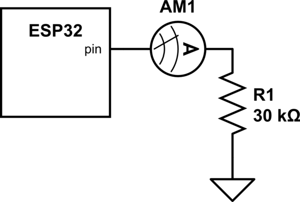
I verified it with the following schematic:

schematic

simulate this circuit – Schematic created using CircuitLab

While running, the current measured is approx 110µA (as expected). During deep sleep, with the old code (in the question, that sets up a weak pull-up), the current falls to ~50µA (so the pull-up resistor value is in the 30k range). With the suggested code here, it stays 110µA.

\$\endgroup\$
3
  • 1
    \$\begingroup\$ Drawing 110µA during sleep of a battery powered device is not a good thing. It might be better than the alternative of letting your load switch on, but it indicates a rather unfortunate circuit design. \$\endgroup\$ Commented Mar 25, 2019 at 19:46
  • 1
    \$\begingroup\$ I agree. The very fact that a weak pull-up is insufficient is a very strong indicator that "something's wrong, pal" :) \$\endgroup\$
    – anrieff
    Commented Mar 26, 2019 at 7:39
  • 1
    \$\begingroup\$ ESP-IDF docs for this function state, "However, on ESP32/S2/C3/S3/C2, this function cannot be used to hold the state of a digital GPIO during Deep-sleep." In my tests this is true. Only the "RTC" GPIOs can use this. For the non-RTC GPIOs, it has no effect. \$\endgroup\$
    – TrentP
    Commented Dec 14, 2023 at 9:37
5
\$\begingroup\$

It's not clear that making the resistor change you propose will be effective at solving your problem.

The MCP160 requires that the enable input is taken below 20% of Vin to effectively switch the device off. If Vin is (say) 5 volts then 20% is 1.0 volts and, because the ULN2003 is a darlington, it may not reliably switch this low. However assuming it does switch lower than 1 volt then there is still the possibility that my guess about the value of Vbatt of 5 volts doesn't cover the low end of the range.

For instance if Vbatt is expected to work down to say 2 volts then you can only switch the MCP160 off if the enable pin is taken to less than 0.4 volts. This sounds all to close for my liking and I would recommend you think about the problem a bit more.

\$\endgroup\$
5
  • \$\begingroup\$ The whole setup there is a blunder caused by an overzealous attempt to reduce partcount. However, because the ULN2003 is a very peculiar chip, the configuration shown actually works with a pull-up. E.g., if you replace the wire between ESP32 and ULN2003 with a resistance, the saturation voltage decreases with increasing resistance (480mV @ 10kΩ, 350mV @ 20kΩ). The lowest Vin is 3.0V, so the design will work, albeit not by a large margin. \$\endgroup\$
    – anrieff
    Commented Jan 15, 2018 at 19:26
  • 2
    \$\begingroup\$ I'm also concerned that the device won't turn on too. The ULN2003 leakage current (when off) is quite high, maybe 50 uA so it does look a bit of a mess. My advice. Nail all the problems and make one hit on the customers to fix all things. If you have to make more than two visits to 1 customer you'll be seen as unreliable. \$\endgroup\$
    – Andy aka
    Commented Jan 15, 2018 at 20:04
  • 1
    \$\begingroup\$ Oh, of course, the next revision will have this (and other) issues fixed reliably. But that will be more than a month in the future and I wanted a stopgap solution, since the data being collected is important (the number of visits isn't). \$\endgroup\$
    – anrieff
    Commented Jan 15, 2018 at 20:46
  • 1
    \$\begingroup\$ You seem like a nice bloke under a bit of pressure to get this right and I’m sorry my answer and comments appear doom and gloom. But you owe it to your business to minimise disruption to your customers because, well, it should be obvious. I’ve only seen barely a block diagram of a snapshot of your circuit so I would highly recommend you get your design hardware reviewed professionally. I’m not in that business btw but you might find it pays dividends. \$\endgroup\$
    – Andy aka
    Commented Jan 15, 2018 at 23:22
  • 1
    \$\begingroup\$ "Customer impression" is unimportant here - it's more of a research project and it's not really for a customer. Eventually, I'd want to become an EE professional and this project is a perfect learning opportunity. \$\endgroup\$
    – anrieff
    Commented Jan 16, 2018 at 9:23
5
\$\begingroup\$

Here's two other links of people who have tried. fail, probably fail.

So it doesn't look promising with solving it in software, as you have tried. So right now there's 3 failures, you and the 2 links.

Proposed solutions:

  • A) Burn a tankful of gasoline
    • Pro: Every device you fix you'll know be functional correctly.
    • Con: A lot of your time and money will be wasted on gas and driving.

  • B) Fix 1 device nearby and make a tiny tutorial for those who got your devices, pay them to solder a pull up resistor, e.g. follow the tutorial. Yes, pay them because they will be doing some work, work that you failed to do during the testing stage of your product.

    • Pro: This will be cheaper, and whoever that has the devices might think less of you professionally, but higher of you in terms of trust.
    • Con: Some people... just fail with simple things, including soldering. So there's a chance that someone will just ruin their device and have to buy another one off you, which you will give away for free, which might be a huge loss.

  • C) Do the same thing as B, but instead of telling whoever that got your devices to do the job, hire some random people who live nearby and can do it for you.

    • Pro: Whoever that has the devices will feel that you're professional.
    • Con: Whatever random person that solves your problem now knows how to properly mess with your instrument.

  • D) Do the same thing as C, but use friends (who might live nearby) or some colleagues instead of some randoms.

    • Pro: Whoever that has the devices will feel that you're professional.
    • Con: Your friends will think you're unprofessional.

  • E) Do what the user DoxyLover proposes, "Fix some units locally and ship them to your users, along with pre-paid return shipping labels so they can ship the originals back to you."


If I were you I'd go backwards, start with E. If that is not an option then continue with D, if you can't then go with C, if you can't then go with B and lastly go with A.

\$\endgroup\$
4
  • 1
    \$\begingroup\$ One more option. Fix some units locally and ship them to your users, along with pre-paid return shipping labels so they can ship the originals back to you. \$\endgroup\$
    – DoxyLover
    Commented Jan 15, 2018 at 17:56
  • \$\begingroup\$ @DoxyLover Probably the best solution. \$\endgroup\$ Commented Jan 15, 2018 at 17:58
  • \$\begingroup\$ Feel free to edit it into your answer. \$\endgroup\$
    – DoxyLover
    Commented Jan 15, 2018 at 18:00
  • \$\begingroup\$ Thanks, my general feeling was that I've trapped myself in a situation where the software can't really fix the hardware mess. Your answer confirms that. As already discussed with @Andy aka, this is more of a research project and "customer impression" is unimportant. Other constraints eliminate options E, D, C. I'll think more about it, but I'm strongly leaning towards A. \$\endgroup\$
    – anrieff
    Commented Jan 15, 2018 at 20:50
3
\$\begingroup\$

After hours of frustration with a similar problem and the answers not giving me a satisfactory solution I found out that the hold functions (should have caught on from the documentation) lock the state of the pin and may prevent them from being modified. In short you'll likely need gpio_hold_dis and gpio_deep_sleep_hold_dis or similar to have features like these work properly.

Here's a quick and more or less complete way to blink an LED (on your gpio pin of choice) using deep sleep.

#include <Arduino.h>

RTC_DATA_ATTR bool blink_value = 0;

void setup() {
  blink_value = !blink_value;
  Serial.begin(9600);
  Serial.println(blink_value);
  pinMode(LED_BUILTIN, OUTPUT);
  //NOTE: the key to getting this to work are these two lines
  //we're effectively putting the esp32 back into its default state w/o any hold feature
  //should probably disable held pins when waking up
  gpio_hold_dis((gpio_num_t) LED_BUILTIN);
  gpio_deep_sleep_hold_dis();

  //NOTE: if we don't release the hold feature here the state that we originally wrote will be permanent as the hold is not released when waking up! 
  //TLDR: make sure to release holds on pins before writing to them when using deep sleep features, otherwise you may be permanently setting them high or low.

  //now we can do whatever we'd like to our pins
  digitalWrite(LED_BUILTIN, blink_value);

  //and now we can setup to go to sleep
  gpio_deep_sleep_hold_en();
  gpio_hold_en((gpio_num_t) LED_BUILTIN);  
  esp_sleep_enable_timer_wakeup(1 * 1000000);
  esp_deep_sleep_start();
}

void loop() {
  //never going to run, but of course you can make this as complicated as you'd like
}
\$\endgroup\$
1
  • \$\begingroup\$ Shouldn't a TLDR be shorter than the NOTE? ;) \$\endgroup\$
    – Velvet
    Commented May 31, 2023 at 12:37
2
\$\begingroup\$

The problem that everyone is missing is that the input current needed to keep the the ULN2003 active sort of defeats any attempt at saving power by putting the microcontroller into deep sleep.

The proper solution is to replace that section of ULN2003 with something that doesn't consume any current such as a MOSFET.

However, I'm wondering why the ULN2003 is in the circuit in that location in the first place. Why can't the microcontroller drive the EN pin on the DC-DC converter directly?

The most that you may have to add is a high-value pull-down resistor from EN to ground.

\$\endgroup\$
2
  • \$\begingroup\$ "Why can't the microcontroller drive the EN pin on the DC-DC converter directly?" - because the EN pin's logic 1 is Vbatt, while the MCU output is 3.3V, so level shifting is required. \$\endgroup\$
    – anrieff
    Commented Dec 20, 2018 at 6:56
  • \$\begingroup\$ Or not. Since you don't need to source current here, just plug the EN pin to the µC in the middle of a high resistive divisor. Set the GPIO as open drain. When set to 0 output, the voltage on the pin will be ~0.3V and when set to input, it'll be Vin * resistor gain. The leakage on the resistor bridge can be small enough, since MCP1640 EN impedance is 1Gohm, you can use ~85.7MOhm for R1 and 14.3M for R2 (total 100M), R2 connected to VBatt. The leakage current is 42nA. \$\endgroup\$
    – xryl669
    Commented Jun 10 at 17:47
2
\$\begingroup\$

It seems that the lib has evolved from @anrieff's answer at Mar.25.

I have implemented this function rather using the RTC APIs of ESP32. Of course this functionality is still intended for low power usages, so I'm using a MOSFET & ESP32 to control another power source.

The official examples are quite useful: https://github.com/espressif/esp-iot-solution/tree/master/examples

Code & comments:

#include <driver/rtc_io.h>
#define SWITCH_PIN GPIO_NUM_4
#define uS_TO_S_FACTOR 1000000ULL  /* Conversion factor for micro seconds to seconds */
#define TIME_TO_SLEEP  5        /* Time ESP32 will go to sleep (in seconds) */

RTC_DATA_ATTR int pinState = 0;

void setup() {
    Serial.begin(115200);

    pinState = (pinState+1)%2; //flipping between on & off

    rtc_gpio_init(SWITCH_PIN); //initialize the RTC GPIO port
    rtc_gpio_set_direction(SWITCH_PIN, RTC_GPIO_MODE_OUTPUT_ONLY); //set the port to output only mode
    rtc_gpio_hold_dis(SWITCH_PIN); //disable hold before setting the level

    rtc_gpio_set_level(SWITCH_PIN, pinState); //set high/low

    esp_sleep_enable_timer_wakeup(TIME_TO_SLEEP * uS_TO_S_FACTOR);

    //gpio_deep_sleep_hold_en();
    rtc_gpio_hold_en(SWITCH_PIN); // enable hold for the RTC GPIO port

    Serial.println("Going to sleep now");
    Serial.flush(); 

    esp_deep_sleep_start(); //sleep
}
\$\endgroup\$
2
\$\begingroup\$

I came up to this QA but I realized there is one more caveat:

The state of digital gpio cannot be held during Deep-sleep, and it will resume the hold function when the chip wakes up from Deep-sleep. If the digital gpio also needs to be held during Deep-sleep, gpio_deep_sleep_hold_en should also be called.

\$\endgroup\$

Your Answer

By clicking “Post Your Answer”, you agree to our terms of service and acknowledge you have read our privacy policy.

Not the answer you're looking for? Browse other questions tagged or ask your own question.