13
\$\begingroup\$

I'm currently working on device that uses always-on 3D accelerometer(using scale +-2g) and 3D gyroscope(using scale +-250g) -sensor.

I can read every possible vector (X,Y,Z) and their acceleration (g's) and angular rate (dps) and also the angle where the device currently is. But my problem is that when the device is on tilt (0g when no tilt) the acceleration is between (downward) 0g->-1g or between (upwards) 0g-> 1g depending on what angle the device currently is. Below is picture that hopefully clears the idea.
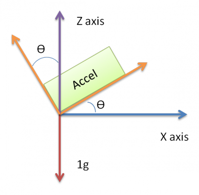
Hopefully this helps

The device will located in a car and should measure acceleration when car is slowing down (brake) . However if the device is already on tilt the accelerometer will measure some acceleration that tilt causes which makes it hard to tell if the device has truly some acceleration or is it just the tilt that causing the acceleration.

X and Y -Axis produce 0g and the Z axis is 1g when device has no tilt and is on flat surface. The tilt causes the reading of X axis to go towards 1g if tilting is towards up and to -1g when downwards. The +-1g is reached when the device is on 90* degree from original position

I have been thinking my head off how to eliminate that acceleration that tilt causes and only measure the real acceleration of the device but just can't think way out from this problem with the following data that i can produce.

Basically i think that if i could only measure the X axis acceleration (picture) even if the sensor is in tilt like in picture.

Hopefully this message isn't too hard too understand because of my english skills and the way I'm trying to explain my problem.

\$\endgroup\$
11
  • 2
    \$\begingroup\$ Why don't you just measure when there is no interesting acceleration happening, and use that as a comparison point? \$\endgroup\$
    – PlasmaHH
    Commented Jan 19, 2018 at 11:11
  • \$\begingroup\$ I think that wouldn't work. If the device is perfectly still X and Y axis are 0g and Z axis 1g. Tilt causes X axis reading be from -1g to 1g depending on tilt, like I stated. The braking causes X axis measured value to decrease (negative acceleration so car is slowing down). If the device is already for example is tilted downwards so it's something between 0g - (-1g) how I can tell that this is not acceleration caused by braking? \$\endgroup\$
    – jumbojohn
    Commented Jan 19, 2018 at 11:37
  • \$\begingroup\$ Why don't you calculate the total acceleration of three axes instead of just Y-axis? I think that is something of basic to consider all three axes right!? Something like this \$\endgroup\$
    – charansai
    Commented Jan 19, 2018 at 11:42
  • \$\begingroup\$ The LSM6DSM does not have a magnetometer. Where did you get this information from? I think you in fact are using the X-NUCLEO-IKS01A1 board from ST, which has both the LSM6DSM Gyro/accelerometer and a LIS3MDL Magnetometer. \$\endgroup\$
    – MrGerber
    Commented Jan 19, 2018 at 14:43
  • \$\begingroup\$ @MrGerber Thank you for noticing that. It was my bad for misreading the datasheet of the sensor. \$\endgroup\$
    – jumbojohn
    Commented Jan 19, 2018 at 14:47

7 Answers 7

18
\$\begingroup\$

Only a sketch of a solution.

Take all 3 axes into consideration.

Acceleration due to gravity, regardless of tilt, will always be 1G, as a vector sum of X,Y,Z, no matter what the tilt. You can picture the acceleration at rest or steady motion as a point on a sphere with radius 1G. (If you are perfectly horizontal, that point will be (0, 0, -1) i.e. directly below you).

Acceleration due to braking will distort the sphere itself; the vector sum of X,Y,Z will no longer be 1G.

So

$$A = \sqrt{X^2 + Y^2 + Z^2}$$

gives you the total acceleration. If it equals G you are at rest; otherwise you are accelerating, and \$A\$ is the vector sum of G and the true acceleration.

You now have to find the true acceleration which will normally be a vector in the forward (or rearward) direction which explains the difference between \$A\$ and G. You need to subtract some point on the G sphere from \$A\$, to find a (hopefully unique solution) vector with only an X (forward/backward) component. That is your acceleration. (I'll leave the trigonometry as a simple puzzle, hopefully the idea is clear).

Unless you are also turning or skidding, so you need inputs from steering wheel and ABS to be sure; that becomes a data fusion problem. This approach will provide an estimate of acceleration. To sanity-check and refine that estimate, combine it with other (also unreliable) data sources, as in Phil Frost's answer, using a Kalman filter.

\$\endgroup\$
6
  • \$\begingroup\$ Actually i have never worked with accelerometer/gyroscope before so the big picture is not fully clear how these things work and math is not one of my strongest skills so I would appreciate the tips/clarification, thanks. \$\endgroup\$
    – jumbojohn
    Commented Jan 19, 2018 at 13:43
  • \$\begingroup\$ While correct I have a strong suspicion that the error margins are going to be important. Also don't forget vertical acceleration will distort the sphere (e.g. speed bumps, potholes) so you may need to solve for that depending on the application. \$\endgroup\$
    – Chris H
    Commented Jan 19, 2018 at 14:42
  • \$\begingroup\$ But gravity isn't constant if you look hard enough. While the highest road in the US only reduces $g$ by about 0.1%, going from the poles to the equator makes a difference of 0.5%. Geology can also make a difference of this order of magnitude. Probably not a game-changer but don't neglect the calibration \$\endgroup\$
    – Chris H
    Commented Jan 19, 2018 at 14:46
  • \$\begingroup\$ You only need to modify the radius of the G sphere according to your location, or measure it before turning the engine on; that's a non issue. I agree that bumps probably need to be handled alongside skids and steering though. \$\endgroup\$
    – user16324
    Commented Jan 19, 2018 at 14:52
  • \$\begingroup\$ Calibrating before starting the engine is the sort of thing I was thinking off. Calibration had be quick though if the builder isn't then end-user. \$\endgroup\$
    – Chris H
    Commented Jan 19, 2018 at 16:09
9
\$\begingroup\$

Your main mistake is in not treating acceleration as a single vector. When the car is at rest, that vector will always be 1 g upwards. Don't look at just the X component of the raw accelerometer data. Do the real vector math.

But my problem is that when the device is on tilt (0g when no tilt) the acceleration is between (downward) 0g->-1g or between (upwards) 0g-> 1g.

No. This is the point. What you are saying may be true for the X component of the accelerometer output, but it is not true for acceleration when the car is at rest.

The ideal measured acceleration will always be the actual acceleration of the car (relative to the earth), plus the 1 g acceleration due to gravity. The latter is always in the up direction. If you know the orientation of the car, then you can subtract off this 1 g due to gravity to find the acceleration you are actually looking for.

Note that there is considerable error in such readings, especially from cheap MEMS sensors. While you should be able to get a good idea about short term events like hard acceleration or hard braking, this data is nowhere near good enough to do inertial navigation for more than a few seconds at best.

\$\endgroup\$
2
  • \$\begingroup\$ Won't the (measured) acceleration due to gravity be in the "up" direction? As in, the reading you'll get from the device at rest in Earth's gravity will be the same as you'd get outside of any gravitational field but accelerating in the (device-relative) "up" direction? \$\endgroup\$
    – psmears
    Commented Jan 19, 2018 at 14:21
  • \$\begingroup\$ @psmears: Yes, you're right. The force is downwards, but the apparent acceleration is upwards. Fixed. \$\endgroup\$ Commented Jan 19, 2018 at 16:19
5
\$\begingroup\$

As other answers have stated, the accelerometer provides a three dimensional vector which is the sum of gravity and other acceleration on the car due to the engine, brakes, or other forces acting on the car. Your objective then is to subtract the gravitational acceleration from the accelerometer's output to find the remaining other forces.

For best accuracy you can't assume gravity is always "down" relative to the accelerometer. For example, the car may be on a hill. All your calculations must be done with three dimensional vector math, and you must have some estimate of the orientation of the car so you know the direction of the gravity vector to subtract.

A Kalman filter is a common approach here. The idea is to take all the data you have which might alter the orientation of the car, then perform a weighted average of the measurements, combine that with what you know about the physics acting on the car, to arrive at a probabilistic estimate of the new orientation of the car and which way is "down".

The more data you have, and the more accurately you can model the physics of the car, the more accurate this estimation can become.

For example, if you have a gyro and you measure the car pitching up, you can predict the gravity vector is going to rotate towards the rear of the car. Over the short term, say when the car has just begun going up a hill, this can help the gravity vector rapidly assume the correct orientation.

You might also assume the car will on average not be braking or accelerating. Thus, a low-pass filtered output of the accelerometer might feed into the estimation of what direction "down" is. This provides a long-term measurement not subject to inertial drift.

Combining data from the accelerometer and gyroscope to estimate the gravity direction thus provides a more accurate estimation than either measurement alone.

You can further incorporate what you know of the possible operational envelope of the vehicle. For example the car can not drive up or down hills that are too steep, so when the accelerometer indicates such extreme angles you might weight it less, assuming most of its output is due to brakes or engine, not gravity.

You know if the driver hits the brakes, this is going to move the acceleration vector, and you can subtract this from the estimated "down" component.

Or if you have GPS and map data, you might incorporate an estimate of the slope of the car based on location. If you have high accuracy data you might know precisely what hill the vehicle is on. If you have only low accuracy data this can still be useful. For example if the car is in Kansas, hills are unlikely. If the car is in San Francisco, hills are more likely and you might give the accelerometer less weight.

If you have data on fuel consumption and speed, knowing that more fuel is consumed when going uphill, you might use this to estimate the car is pitched up or down based on fuel efficiency.

And so on. The more you know, the better your estimate can be.

\$\endgroup\$
3
\$\begingroup\$

You would need a fusion algorithm and use 3D-accelerometer, 3D-Gyro and 3D-Magnetic sensors. With this fusion algorithm you get the attitude, the earth gravity helps as reference to detect the horizon - pitch/yaw/roll angles. The other two sensors mag/gyro helps to filter out the dynamic movement. As you car will also turn left/right,..the centrifugal force will be added. Once you have the attitude, then you can subtract the gravitational vector and disassemble the resultant acceleration in all three axes.

\$\endgroup\$
3
\$\begingroup\$

As a very basic approach, you can use a high-pass filter to eliminate the constant part of the acceleration (which corresponds to gravity) and keep the variable part of which is due to car dynamics. Suppose raw is a vector containing your X, Y and Z measurements, and acc is the car acceleration without gravity. Then

void correct_for_gravity(float *raw, float *acc)
{
   const float k = 0.9;
   static float gravity[3];

   gravity[0] = k * gravity[0] + (1 - k) * raw[0];
   gravity[1] = k * gravity[1] + (1 - k) * raw[1];
   gravity[2] = k * gravity[2] + (1 - k) * raw[2];

   acc[0] = raw[0] - gravity[0];
   acc[1] = raw[1] - gravity[1];
   acc[2] = raw[2] - gravity[2];
}

Individual components of acc are still affected by tilt, but the vector norm isn't:

norm_acc = sqrt(acc[0]*acc[0] + acc[1]*acc[1] + acc[2]*acc[2]);

Of course, this method is not very precise, especially if the tilt changes at a high rate. This is about as far as naive math gets you. If you need better precision, learn how to use a Kalman filter.

\$\endgroup\$
1
\$\begingroup\$

The answer lies in the precise definition of "slowing down".

From your question:

The device will located in a car and should measure acceleration when car is slowing down (brake).

However, slowing down does not equal braking. There are two possible definitions:

  1. The speed of the car relative to ground is decreasing.
  2. The car brakes are being applied.

This difference is significant in uphills and downhills. In downhills, the speed of the car will increase if brakes are not applied. And in uphills, the speed can slow down even when not braking.

It turns out that detecting 1. is significantly more difficult than 2. Let's define axes as relative to the car orientation: X: front-back direction, Y: left-right direction, Z: up-down direction. All axes aligned to car.

Solutions:

  1. For definition 1., the best approach is to assume that the speed of the car can only change in X direction. Then the measured acceleration a = g + v where g is acceleration due to forces countering gravity, and v is acceleration due to velocity change. You can assume the length of g is always equal to 9.8 m/s², and that v is always in X direction. So (g_x + v_x, g_y, g_z) = (a_x, a_y, a_z), which gives v_x = a_x - sqrt((9.8m/s²)² - g_y² - g_z²). This will only work as long as |v| is less than |g|, or in other words, the acceleration due to motor or brakes is less than 1G. Should be pretty safe assumption unless your car has a rocket booster.

  2. For definition 2., you can just take the x-axis reading directly. If the car is not accelerating or braking, the only gravity-countering force acting on it is the normal force of the road surface. This force is always in the z-direction relative to car, so it doesn't change the x-axis reading. Brakes and motor act only in the x-direction, and will be directly visible in this reading.

\$\endgroup\$
0
\$\begingroup\$

It seems that you are using an "overkill" device for your application. You should use a device that only measure x & y acceleration, this way, the tilt will have no measurable effect. Although the total acceleration may be smaller or larger, due to the tilt, the device will measure only the x & y components of the acceleration on the plane the vehicle is on.

\$\endgroup\$

Your Answer

By clicking “Post Your Answer”, you agree to our terms of service and acknowledge you have read our privacy policy.

Not the answer you're looking for? Browse other questions tagged or ask your own question.