6
\$\begingroup\$

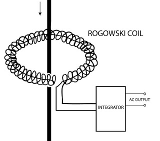
Rogowski coils measure current by completing a loop of coils around the conductor seen below.

enter image description here

This makes sense, but question 1: This is a current transformer, and transformers couple, so in this system when the Rogoski coil couples with the measured wire, does this not affect/damage the measured wires current (we are measuring) as we are drawing/collapsing its magnetic field in order the induce a voltage in the coil?

Question 2: Why can the circuit diagram below not do the same job? The Rogowski coil only works when you form a loop around the conductor. Why does the Rogowski coil only work when its a closed loop? Why can a coil no just be in parallel with a wire and measure current?
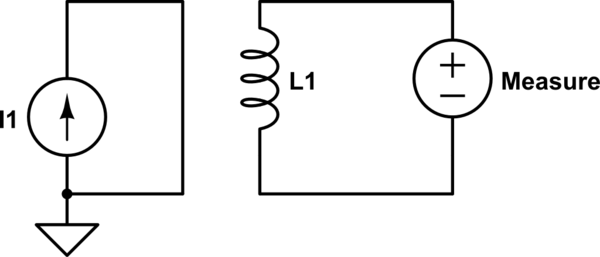
schematic

simulate this circuit – Schematic created using CircuitLab

The right hand rules says that in the coils are wound in the correct direction, in the circuit diagram would couple the magnetic field the current is inducing.

Image source: http://www.electrotechnik.net/2009/09/what-is-rogowskis-coil.html

\$\endgroup\$
0

4 Answers 4

14
\$\begingroup\$

A Rogowski coil is not a current transformer.

The current in the main conductor generates a magnetic field round itself. The Rogowski coil samples the field, generating a voltage as the field changes. It is weakly coupled to the main conductor. As little, ideally no, current flows in the Rogowski coil, there is no effect back on the main conductor.

Any loops couple. The sampling coil would generate a voltage whether it formed a closed loop around the main conductor or not. However, that's not terribly useful, as the coupling, and hence the generated voltage, would change if the conductors changed position. The sampling coil would also respond to any current changes anywhere in the vicinity.

The reason the Rogowski coil takes the form of a uniform toroidal winding is because due to the symmetric situation, it couples to all the current flowing within the toroid, regardless of the position of the conductor. There is zero coupling to any current that does not pass through the hole. An incomplete circle, or a non-uniform winding, would not have these two desirable properties.

\$\endgroup\$
5
\$\begingroup\$

A Rogowski coil senses AC current.

This is a current transformer, and transformers couple...

This is certainly a transformer (one magnetic circuit, with two or more windings), but 'current transformer' implies a high coupling (nearly 1), and a low impedance on the secondary, both of which do not apply here.

Why can a coil no just be in parallel with a wire and measure current?

[as in, a helical coil with the helix axis parallel to the primary wire]

The coupling in a Rogowski coil comes from the inner semicircle parts being close to the sensed wire, while the outer semicircle of the wire is farther away. Both semicircles are roughly parallel to the sensed wire, so they couple, but the inner half couples more strongly than the outer half. Thus, the positive coupling on the inside and negative coupling on the outside do not quite cancel entirely. The 'return' wire is not parallel to the primary, and its path inside the R-coil is insensitive to the current being measured.

The coupling of the R-coil is determined by that coil geometry without regard to the return wires going to the integrator. The 'helix-in-parallel' would have coupling due to the wires from the ends of the solenoid as they are routed to the integrator. Coiling (other than as it moves the wire path closer/farther from the primary) of the solenoid is not productive.

The R-coil does NOT have full flux coupling, so an open circuit on the Rogowski coil only loads the primary winding with the same series inductance (maybe a microhenry per meter) as any wire in space; a closed circuit on the Rogowski coil would only change that by a few parts per million.

The EMF in the Rogowski coil is produced as a side effect of the self-inductance of the primary wire. Using the side-effect means one can measure with no significant energy cost.

\$\endgroup\$
2
\$\begingroup\$

1: The load impedance is high so there is no burden to the source.
2: L1 is not shown as a transformer.

enter image description here

The key to the circuit is the Mutual inductance , L which capture the magnetic flux that only flows thru the primary wire.

For peak of a square wave, V=L*di/dt then integrated to become Vout = I * k for k = calibration const.
For a sine wave V = ωLI the same units of peak, or RMS as desired.

\$\endgroup\$
2
  • \$\begingroup\$ A Rogowski coil has no ferrite or iron core as a CT does. \$\endgroup\$
    – user105652
    Commented Jan 19, 2018 at 21:38
  • \$\begingroup\$ @Sparky256 < true but air still has permeability and mutual coupling. \$\endgroup\$
    – D.A.S.
    Commented Jan 19, 2018 at 22:45
0
\$\begingroup\$

more simple based on energy laws:

there is no substantial difference (in theory) between a transformer and this. Both used induction, BUT a transformer works with the scope to transfer energy, so typically efficiency is 90%.

this circuit is thought to measure, so follows the basic rule of measurement: do NOT modify what You want to measure, so do NOT sink energy.

And above circuit has so little induction that energy sunk is very small, and current sunk must be conveyed to an opamp, usually (so µA or nA are involved)

\$\endgroup\$

Your Answer

By clicking “Post Your Answer”, you agree to our terms of service and acknowledge you have read our privacy policy.