1
\$\begingroup\$

I have a design that uses an ATXMega32E5 for two audio sources. In one case, a timer output square wave (3.3v logic) goes through a low-pass filter to make beeps, and in the other case, a DAC channel outputs 8 kHz audio samples (0-3.3v). Each goes into a 20k pot, the output of which goes into an LM4871, and into an 8Ω speaker.

The audio sounds fine, but the levels are way too low - like hold the speaker next to your ear.

I tried cranking up the LM4871 gain a little, but you're not really supposed to do that, and 3 dB of gain from the reference design didn't really make much of a difference I could hear.

I'm thinking the correct thing to do is stick an op amp (inverting configuration with half-vcc virtual ground) gain stage in.

Audio isn't really my strong suit. Can someone look over the proposed design and tell me what's wrong with it? :)

The original circuit just connects the R8/R13 output directly to C23. Everything between those two points is the addition I'm thinking of.

Note that during the test, AUDEN is high - with AUDEN low, there's no audio at all (which is the whole point of that line). schematic
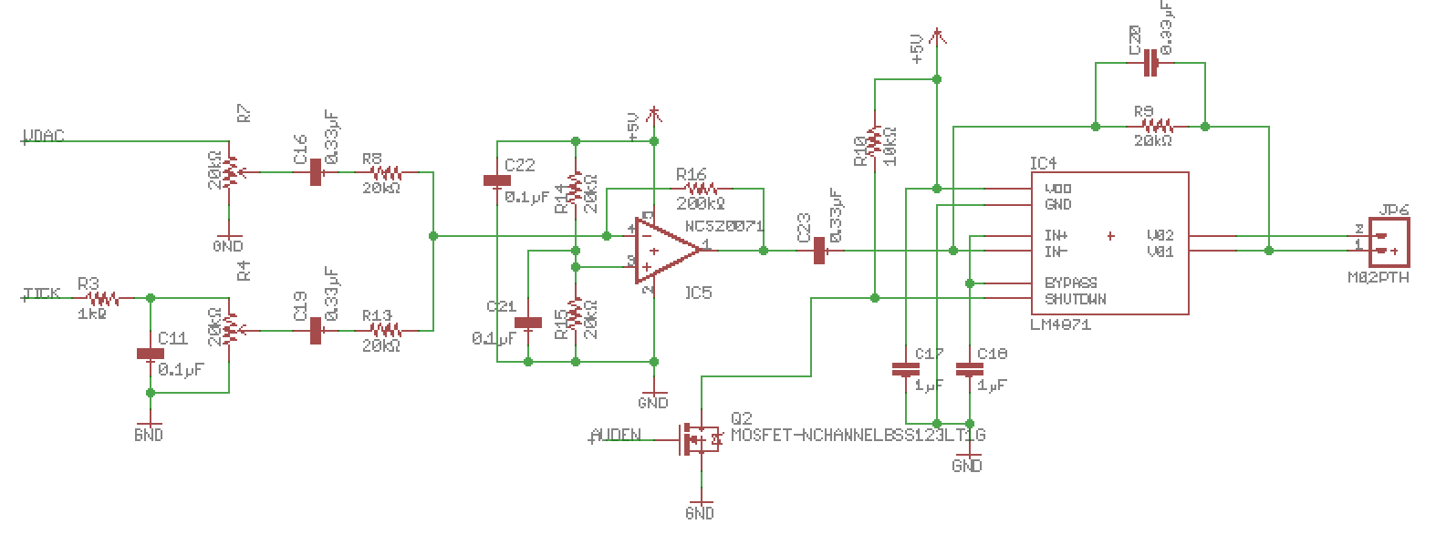
P.s. The differential output on the speaker leads (with the speaker attached) is around 2v P-P. Is it perhaps just that this speaker sucks?

\$\endgroup\$
9
  • \$\begingroup\$ LM4871 datasheet shows 20k in series with C23 [fig 3-typical circuit]. Have you left that out intentionally? \$\endgroup\$
    – vofa
    Commented Jan 21, 2018 at 6:40
  • \$\begingroup\$ No. Someone on Twitter also mentioned that. I’m going to call that an error. 😁 \$\endgroup\$
    – nsayer
    Commented Jan 21, 2018 at 7:10
  • \$\begingroup\$ With peak to peak DAC and beeper output voltage in the volts range you will never need extra amplification, LM4871 is quite enough. Search for error somewhere else. \$\endgroup\$
    – carloc
    Commented Jan 21, 2018 at 9:56
  • \$\begingroup\$ @carloc That's kind of what I was thinking at the time. My conclusion was that the controller didn't have sufficient output drive for the input impedance, but that just doesn't seem reasonable. \$\endgroup\$
    – nsayer
    Commented Jan 21, 2018 at 16:16
  • \$\begingroup\$ You are right, I'd rather search for some trivial error, maybe just some part or connection broken, a wrong pinout or something alike... \$\endgroup\$
    – carloc
    Commented Jan 21, 2018 at 16:20

2 Answers 2

0
\$\begingroup\$

IC4 is configured wrong for negative feeedback. Check datasheet.

Remove C20

Insert 20k with C23 in series for unity gain

\$\endgroup\$
2
  • \$\begingroup\$ C20 ostensibly adds some low-pass filtering to the output stage. The configuration of the amp itself is correct according to the data sheet. I believe you’re right about adding 20k in series to C23, though. \$\endgroup\$
    – nsayer
    Commented Jan 21, 2018 at 7:11
  • \$\begingroup\$ Get a DMM if you want to stop guessing. Measure all continuity, DC AC all points start from input \$\endgroup\$
    – D.A.S.
    Commented Jan 21, 2018 at 12:59
0
\$\begingroup\$

A commenter on my hackaday project solved the mystery. I had calculated the rolloff frequency for the LM4871 feedback incorrectly. With 0.33µF it's something like 24 Hz instead of 2.4 kHz like I wanted. Replacing it with 1000pF brought the audio right up (but 2200pF is probably a better choice).

I'd already ordered new boards with the preamp circuit, but I can always leave all of the components off and use 0Ω for the preamp feedback resistor (R16) and see which way is better.

\$\endgroup\$

Your Answer

By clicking “Post Your Answer”, you agree to our terms of service and acknowledge you have read our privacy policy.

Not the answer you're looking for? Browse other questions tagged or ask your own question.