3
\$\begingroup\$

schematic

simulate this circuit – Schematic created using CircuitLab

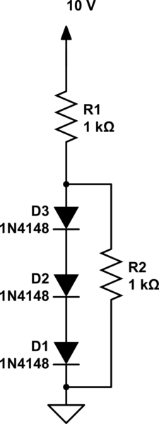
Hi, Question: In the following, a string of three diodes is used to provide a constant voltage of about 2.1 V. We want to calculate the percentage change in this regulated voltage caused by (a) a ± 10% change in the power-supply voltage and (b) connection of a 1-kΩ load resistance. Assume n = 2.

I had some doubts regarding the small signal analysis to be carried out in part B. After asking here, I got enough help to understand and solve it. But the next passage in the book (Microelectronic Circuits) states that while using small signal analysis we get enter image description here.

But if we follow the detailed calculations using the exponential model we would get enter image description here.

I am not able to understand how to derive the answer using the exponential model. What are the steps to find the solution using the exponential model?

Link (to the previously asked question: Diode Modelling)

\$\endgroup\$
2
  • \$\begingroup\$ By changing the current you change the temperature of the diode, assuming it is high enough to overcome ambient temperatures. Their forward voltage goes lower with rising temperature, but not more than 100 mV, and it would take extreme heat to do that much change. \$\endgroup\$
    – user105652
    Commented Jan 23, 2018 at 2:06
  • \$\begingroup\$ We don't have the book pages in front of us. It does make sense that the exponential model would yield different results. What does NOT make sense is that the exponential model would result in a smaller \$\Delta v_o\$ magnitude. Not only is the difference in current slightly more (\$2.1\:\text{ma}\$ vs \$2\:\text{mA}\$), but the linear interpolation would predict, looking backwards towards a lower current, a voltage value that is above what the actual exponential curve is doing. So the actual \$\Delta v_o\$ should be larger than the linear slope prediction projects. (By 2.4 mV or so.) \$\endgroup\$
    – jonk
    Commented Jan 23, 2018 at 5:27

2 Answers 2

2
\$\begingroup\$

Writing down KCL equations in \$v_{OUT}\$, while assuming all diodes are equal such that \$v_D = \frac{v_{OUT}}{3}\$ (current flowing in = current flowing out):

\$\frac{10V-v_{OUT}}{R_1} = \frac{v_{OUT}}{R_2} + I_s\left(e^{\frac{v_{OUT}}{3n\ U_t}}-1\right)\$

This is a transcendental equation that cannot be solved analytically. It should be solved using a numerical method, which is what circuit simulators do.

\$\endgroup\$
1
\$\begingroup\$

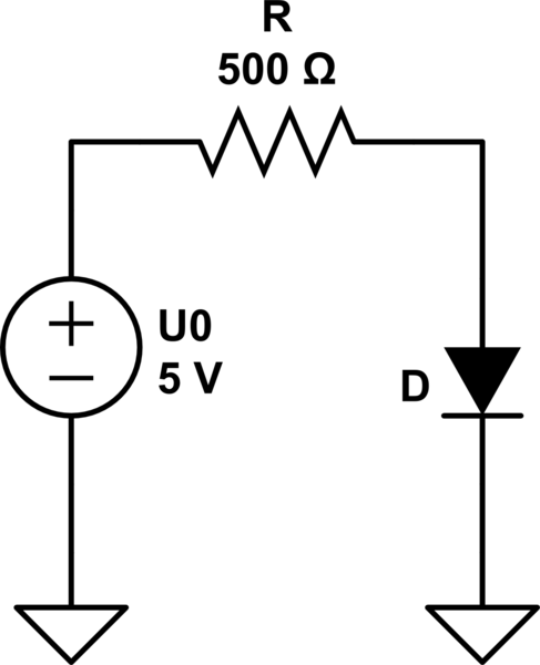
First you can replace the voltage source and voltage divider by its Thevenin equivalent and the three diodes by one which has just different parameters:

schematic

simulate this circuit – Schematic created using CircuitLab

Assuming the diodes are modelled by the Shockley diode equation
\$I(U) = I_s (e^{\frac{U}{U_c}} - 1)\$
then the combined diode (tripple diode) can be modelled by
\$I(U) = I_s (e^{\frac{U}{3U_c}} - 1)\$

So the problem looks simpler; basically there is no difference compared to a circuit with voltage source, one resistor and one diode.

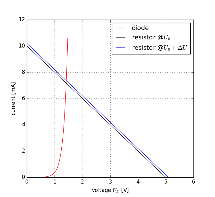
Now look at the I-U graphs of diode and resistor and the load line:

enter image description here As you can see the curvature of the diodes I-U-line (red) doesn't change much in the region where it intersects the load lines (black, blue).

You can calculate the voltage at which the load lines intersect approximately the diodes line using linear approximation.

The difference of the voltages of the intersection will be much smaller than \$\Delta U\$ because the diodes graph is much steeper in that region than the load line.

\$\endgroup\$

Your Answer

By clicking “Post Your Answer”, you agree to our terms of service and acknowledge you have read our privacy policy.

Not the answer you're looking for? Browse other questions tagged or ask your own question.