3
\$\begingroup\$

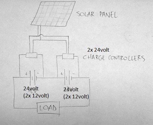
I have 2 sets of 2 lead-acid batteries connected in series to produce 48V. They are powering an audio amplifier.

I'd like to be able to charge them with ONE solar panel. If I connect the output of the solar panel to both charge controllers, a short circuit occurs.

What can be done to make this possible?

I made a drawing to illustrate what I'd like to achieve.

enter image description here

\$\endgroup\$
0

4 Answers 4

2
\$\begingroup\$

Taking the question at face value, ALL the answers given are wrong [ :-) ] and your question and a subsequent comment do not match.

You say you have 4 x 12V batteries to make a 48V supply.

Your diagram implies (but does not state) that the panel is 24V rated.

In a comment you say

I don't think I know the PV array's knew voltage. I know it produces up to 18V in full sunlight though. – Wurlitzer Jul 10 '12 at 23:00

An 18V O/C panel is 12V rated, not 24V as per diagram.

Cheap and nasty solution:

Use a relay (or relays) to swap the panel between batteries. Either two positions if 24V panel or 4 positions if 12V panel.

A simple sequencer will be required to control the relays.

Very fast swapping rate reduces relay lifetime, and controller will take a time to settle so "dead time" % is higher.

Very slow swapping rate increases risk of imbalance.
If you swapped every minute or even every 5 minutes the long term differences will be minimal.

A good "real" solution is to use a 48V panel - or 2 x 24V or 4 x 12V panels in series.

Also suitable would be to use a 12V to 48V converter. Some MPPT controllers are available which will both up-convert the input voltage and also optimise loading to maximise panel power output.
\$\endgroup\$
2
\$\begingroup\$

The easiest solution is to get a charge controller with 24 V output. Otherwise, you'd need two separate charge controllers, each isolated from the input. That is not generally how they work, so that would be more difficult to find and more expensive if you do find it.

\$\endgroup\$
5
  • \$\begingroup\$ Thanks for the answer. I should have been more specific. The battery bank actually consists of four batteries, where two 24V charge controllers are charging two pairs of batteries. I thought it would be simpler to describe the system like in my original post. \$\endgroup\$
    – Wurlitzer
    Commented Jul 10, 2012 at 22:12
  • 1
    \$\begingroup\$ @Wurlitzer: You really should describe your actual problem, otherwise you're just jerking around people volunteering their time to give you free help. Those asking aren't usually the best judge of what is relevant and what may change solution parameters considerably. \$\endgroup\$ Commented Jul 10, 2012 at 23:25
  • \$\begingroup\$ Definitely. I tried to simplify my problem in order to make it as clear as possible, but I realize that the simplification introduces other ways to solve it, that are not what I look for. How should I reformulate my problem? Post a new topic, or edit this one? \$\endgroup\$
    – Wurlitzer
    Commented Jul 10, 2012 at 23:45
  • \$\begingroup\$ @Wurlitzer You should edit this one. \$\endgroup\$
    – Kortuk
    Commented Jul 11, 2012 at 2:01
  • \$\begingroup\$ An 18V_OC panel is designed for 12V lead acid use. Vmax power will be about 80% to 85% Voc = 14.4V - 15.3V. Lead acid needs 13.8V max on std charge and higher again for boost. To charge 24V battery you either need a 24V nominal panel (36V OC) or a boost converter or to rewire batteries during charging . \$\endgroup\$
    – Russell McMahon
    Commented Jul 11, 2012 at 5:23
1
\$\begingroup\$

A Single 24volt charger would definitely be the easiest and cheapest way to go, however...

If you can spare the $$$ 2x 12volt chargers as you have shown in the diagram would be the way to go. This will give you a nice balanced battery. Usually balanced batteries have LiPo chemistry because of how volatile they are, however, the same technique can be applied to a Pb battery. This will give you longer lasting batteries and more complete "fully charged" state.

\$\endgroup\$
0
\$\begingroup\$

What is the knee voltage on your PV array? 12 ? 14 ? 16V?

If I wanted efficient 24V~28V storage power and I would choose an a PV array to match the batteries. e.g. 48 cells in series * 0.6V = 28.8V near 100% current. ( no converter just a voltage limiter.)

Max power transfer from current source PV panel is at knee voltage of panel.

\$\endgroup\$
3
  • \$\begingroup\$ so you are trying to charge four 12V lead acid batteries in 2s2p matrix where cell matching must be better than 3% for series use and < 1% for parallel use without parallel leakage issues. using two parallel charge controllers. Hmm NG. I would rewire PV array for 24V and attempt 2s2p battery array but monitor imbalanced current. Check S.G. and monitor cell voltage and S.G. of every cell. \$\endgroup\$
    – D.A.S.
    Commented Jul 10, 2012 at 23:00
  • \$\begingroup\$ I don't think I know the PV array's kneww voltage. I know it produces up to 18V in full sunlight though. \$\endgroup\$
    – Wurlitzer
    Commented Jul 10, 2012 at 23:00
  • \$\begingroup\$ It should look like a zener with two quasi linear load lines. The knee of the curve is around 0.6V per PV cell is ideal for power transfer and 2.35 per battery cell. So sum up cells to match for max power transfer. It will work less efficient otherwise. In order to see power transfer curve, you need an active load monitoring V vs I on scope and 16V is V o.c. \$\endgroup\$
    – D.A.S.
    Commented Jul 10, 2012 at 23:03

Your Answer

By clicking “Post Your Answer”, you agree to our terms of service and acknowledge you have read our privacy policy.

Not the answer you're looking for? Browse other questions tagged or ask your own question.