0
\$\begingroup\$

My code for logical-right shift is as follows:

ENTITY Ror32 IS
PORT(
a_in : IN STD_LOGIC_VECTOR(31 DOWNTO 0);
result : OUT STD_LOGIC_VECTOR(31 DOWNTO 0)
);
END Ror32;

ARCHITECTURE ror_inAction OF Ror32 IS begin

    result(30 downto 0) <= a_in(31 downto 1);
    result(31) <= '0';

end ror_inAction;

My code for left shift is as follows:

ENTITY rol32 IS
PORT(
a_in : IN STD_LOGIC_VECTOR(31 DOWNTO 0);
result : OUT STD_LOGIC_VECTOR(31 DOWNTO 0)
);
END rol32;

ARCHITECTURE rol_inAction OF rol32 IS begin

    result(31 downto 1) <= a_in(30 downto 0);
    result(0) <= '0';

end rol_inAction;

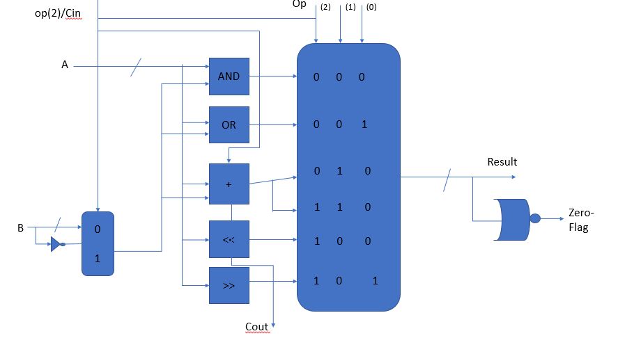
This is the circuit I wanted to program:

enter image description here

My program for the diagram above is as follows:

ENTITY ALU IS
PORT(
a : IN STD_LOGIC_VECTOR(31 DOWNTO 0);
b : IN STD_LOGIC_VECTOR(31 DOWNTO 0);
op : IN STD_LOGIC_VECTOR( 2 DOWNTO 0);
result : OUT STD_LOGIC_VECTOR(31 DOWNTO 0);
cout : OUT STD_LOGIC;
zero : OUT STD_LOGIC);
END ALU;


ARCHITECTURE description OF ALU IS 

-- 2-to-1 MUX
COMPONENT mux2_1
 PORT(
 A,B : in STD_LOGIC_VECTOR(31 DOWNTO 0);
S: in STD_LOGIC;
Z: out STD_LOGIC_VECTOR(31 DOWNTO 0));
 END COMPONENT;

-- NOT
 COMPONENT not32
 PORT(
 x: IN STD_LOGIC_VECTOR(31 DOWNTO 0);
 y: OUT STD_LOGIC_VECTOR(31 DOWNTO 0)
 );
 END COMPONENT;

-- AND
 COMPONENT and32
 PORT(
 a : IN STD_LOGIC_VECTOR(31 DOWNTO 0);
b : IN STD_LOGIC_VECTOR(31 DOWNTO 0);
cout : OUT STD_LOGIC_VECTOR(31 DOWNTO 0)
 );
END COMPONENT;

-- OR
COMPONENT or32
 PORT(
 a : IN STD_LOGIC_VECTOR(31 DOWNTO 0);
b : IN STD_LOGIC_VECTOR(31 DOWNTO 0);
cout : OUT STD_LOGIC_VECTOR(31 DOWNTO 0)
);
END COMPONENT;

-- ADDER
COMPONENT add32
 PORT(
 a_in : IN STD_LOGIC_VECTOR(31 DOWNTO 0);
b_in : IN STD_LOGIC_VECTOR(31 DOWNTO 0);
c_in:  IN STD_LOGIC;
result : OUT STD_LOGIC_VECTOR(31 DOWNTO 0);
c_out : OUT STD_LOGIC
 );
 END COMPONENT;

 -- LEFT-SHIFT
 COMPONENT rol32
 PORT(
 a_in : IN STD_LOGIC_VECTOR(31 DOWNTO 0);
result : OUT STD_LOGIC_VECTOR(31 DOWNTO 0)
 );
 END COMPONENT;

-- RIGHT-SHIFT
 COMPONENT Ror32
 PORT(
 a_in : IN STD_LOGIC_VECTOR(31 DOWNTO 0);
result : OUT STD_LOGIC_VECTOR(31 DOWNTO 0)
 );
 END COMPONENT;

-- 6-to-1 MUX
COMPONENT mux6to1
 PORT(
A,B,C,D,E,F: in STD_logic_vector (31 downto 0);
      S: in std_logic_vector(2 downto 0);
      O: out std_logic_vector(31 downto 0)
);
END COMPONENT;

--Check result
COMPONENT zeroChecker
PORT(
Out_ALU: IN STD_LOGIC_VECTOR(31 downto 0);
Out_Zero: OUT STD_LOGIC
);
END COMPONENT;

--1-bit NOT-gate
COMPONENT notGate
PORT(
ain: in std_logic;
aout: out std_logic
);
END COMPONENT;

------- Intermediate Signals

--signals going to 2-to-1 mux
signal B_inv: STD_LOGIC_VECTOR(31 DOWNTO 0);

--signal coming out of 2-to-1 mux
signal B_res: STD_LOGIC_VECTOR(31 DOWNTO 0);

--signal coming out of AND
signal AND_result: STD_LOGIC_VECTOR(31 DOWNTO 0);

--signal coming out of OR
signal OR_result: STD_LOGIC_VECTOR(31 DOWNTO 0);

--signal coming out of ADD
signal ADD_result: STD_LOGIC_VECTOR(31 DOWNTO 0);

--signal coming out of SUB
--signal SUB_result: STD_LOGIC_VECTOR(31 DOWNTO 0);

--signal coming out of ROL
signal ROL_result: STD_LOGIC_VECTOR(31 DOWNTO 0);

--signal coming out of ROR
signal ROR_result: STD_LOGIC_VECTOR(31 DOWNTO 0);

--signal passing into OR gate
signal Zero_check: STD_LOGIC;

--signal to store the Result
signal Res_intermediate: STD_LOGIC_VECTOR(31 DOWNTO 0);

----Mapping signals and ports

BEGIN


MuxNo1: mux2_1 port map (A=>b, B=> B_inv, S=> op(2), Z=> B_res);

NotForB: not32 port map (x=> B, y=> B_inv);

And_Block: and32 port map (a=> A, b=> B_res, cout=> AND_result);

Or_Block: or32 port map (a=> A, b=> B_res, cout=> OR_result);

Add_Block: add32 port map (a_in=> A, b_in=> B_res, c_in=> op(2), result=> ADD_result, c_out=> cout);

Right_Block: Ror32 port map (a_in=> A, result=> ROR_result);

Left_Block: rol32 port map (a_in=> A, result=> ROL_result);

Final_Mux: mux6to1 port map (A=> AND_result, B=> OR_result, C=> ADD_result, D=> ADD_result, E=> Ror_result, 
                                        F=> rol_result, S=> op, O=> Res_intermediate);


Zero_OR: zeroChecker port map (Res_intermediate, Zero_check);

FinalNot: notGate  port map (ain=> Zero_check, aout=> zero);

result <= Res_intermediate;

END description;

Strangely enough, the Carry-out signal changes as the value of B (the input that has no connection with the logical shift operations) changes.

When the value of B is low, Carry-out becomes active high:

enter image description here

Carry-out becomes active low when the value of B is higher:

enter image description here

The 32-bit adder is the only entity that explicity deals with Carry-Out:

ENTITY add32 IS
PORT(
a_in : IN STD_LOGIC_VECTOR(31 DOWNTO 0);
b_in : IN STD_LOGIC_VECTOR(31 DOWNTO 0);
c_in:  IN STD_LOGIC;
result : OUT STD_LOGIC_VECTOR(31 DOWNTO 0);
c_out : OUT STD_LOGIC
);
END add32;

ARCHITECTURE add32_inAction OF add32 IS 
 component fulladd is
 port(
    a: IN STD_LOGIC;
     b: IN STD_LOGIC;
     cin: IN STD_LOGIC;
     sum: OUT STD_LOGIC;
     cout: OUT STD_LOGIC
     );
  end component;

-- signal wire:STD_LOGIC_VECTOR(30 DOWNTO 0);

    signal wire: STD_LOGIC_VECTOR(32 DOWNTO 0);

 begin

    wire(0) <= c_in;
    FA_f: for i in 0 to 31 generate
        FA_i: fulladd PORT MAP
        (a_in(i), b_in(i), wire(i), result(i), wire(i+1));
    end generate FA_f;

    c_out <= wire(32);
end add32_inAction;

I don't understand the cause of this behavior. Firstly, I don't understand how Carry-out is being influenced by my shift operations. In addition to that, I find it even more puzzling that changes in B are changing the state of the Carry-Out signal. I did not write the code for such a behavior to occur.

EDIT:

Thanks to the answer given by Dave Tweed, I now know that I connected the carry-out bit of the Adder/Subtractor unit with the carry-out bit of the ALU in my top-level file. I shall look into it more closely now.

EDIT 2:

As Dave Tweed pointed out, op(2) is connected to Carrry-In and the Carry-Out of my adder is connected to the cout of my ALU. So, when I select any operation where op(2) is 1 (SUB, ROL and ROR), the carry-out, IF generated, will appear in my wave-forms window. This is because SUB (which generates the carry-out in most cases) is occurring in parallel (as are all the other operations) and it's carry-out is connected to the ALU's carry-out so it will appear in the wave-forms window.

\$\endgroup\$
3
  • 1
    \$\begingroup\$ Welcome to the site. This looks to me like a homework question. If you designed the logic circuit (or 'wrote the code' as you call it') yourself then you would know why this behaviour occurs because you made it do so. Voting to close. Recommend that you edit your question to show your workings so far and to explain your thinking when designing all of this VHDL circuit. \$\endgroup\$
    – TonyM
    Commented Feb 8, 2018 at 7:07
  • 1
    \$\begingroup\$ Your first action when coming across a problem like this should be to carefully and slowly go through the code several times, really making sure that you understand what's going on. If you go to somebody else for help straight away, you won't learn anything. As a start, since your issue is with cout, you might want to look at how that cout port is driven in your top level ALU file. \$\endgroup\$
    – scary_jeff
    Commented Feb 8, 2018 at 9:10
  • 1
    \$\begingroup\$ @TonyM I DID write this code by myself. I am a beginner in VHDL programming and not yet well versed in testing VHDL programs. I tested the left and right shift operations several times prior to posting this question. \$\endgroup\$
    – a_sid
    Commented Feb 8, 2018 at 16:11

1 Answer 1

2
\$\begingroup\$

I did not write the code for such a behavior to occur.

Yes, you did.

c_out of your Add_Block is always connected directly to cout of your ALU, regardless of the value of op. And the adder always responds to the values of both the A and B inputs. Note also that MuxNo1 always responds to the value of op(2).

What you are seeing is exactly what you wrote. Probe the internal signals to see for yourself. This is a habit you should develop whenever things don't seem to be behaving as expected.


Side comment: VHDL is a verbose language to begin with, and you have compounded matters by at least an order of magnitude by using a lot of source code to describe what is really a very simple function — to the point where you've completely obfuscated the details that led to the issue above. You need to learn to use the power of the language to make the actual functionality of a module as clear as possible. This will help both yourself and others who need to read your code.

Just to give you a general idea, here's how the ALU could be written as a single concise module. Note how cout implicitly gets the correct value for every value of op.

library ieee;
use ieee.std_logic_1164.all;
use ieee.numeric_std_unsigned.all;

ENTITY ALU IS
  PORT (
    a      : IN  STD_LOGIC_VECTOR(31 DOWNTO 0);
    b      : IN  STD_LOGIC_VECTOR(31 DOWNTO 0);
    op     : IN  STD_LOGIC_VECTOR( 2 DOWNTO 0);
    result : OUT STD_LOGIC_VECTOR(31 DOWNTO 0);
    cout   : OUT STD_LOGIC;
    zero   : OUT STD_LOGIC);
END ALU;

ARCHITECTURE description OF ALU IS
  ------- Intermediate Signals
  signal a_res: STD_LOGIC_VECTOR(32 DOWNTO 0);
  signal a_res: STD_LOGIC_VECTOR(32 DOWNTO 0);
  signal carry_in: STD_LOGIC_VECTOR(32 DOWNTO 0);
  signal res_intermediate: STD_LOGIC_VECTOR(32 DOWNTO 0);

BEGIN
  -- This is an extended version of A, required for add/subtract
  a_res <= "0" & a;
  -- This is your 2-to-1 mux and the "not B" function, extended
  b_res <= "0" & not b when op(2) = '1' else "0" & b;
  -- This is an extended version of carry-in
  carry_in <= X"00000000" & op(2);

  -- This is your 6-to-1 mux and the logic/arithmetic/shift functions
  process (a_res, b_res, carry_in)
  begin
    case op is
      when "000" => res_intermediate <= a_res and b_res;           -- AND
      when "001" => res_intermediate <= a_res or b_res;            -- OR
      when "010" => res_intermediate <= a_res + b_res + carry_in;  -- ADD
      when "110" => res_intermediate <= a_res + b_res + carry_in;  -- SUB
      when "101" => res_intermediate <= "0" & a_res(32 downto 1);  -- ROR
      when "100" => res_intermediate <= a_res(31 downto 0) & "0";  -- ROL
      when others => -- TBD         
    end case;
  end process;

  -- Zero checker and final NOT
  zero <= '1' when res_intermediate(31 downto 0) = X"00000000" else '0';

  -- Output assignments   
  result <= res_intermediate(31 downto 0);
  cout   <= res_intermediate(32);

END description;
\$\endgroup\$
6
  • 1
    \$\begingroup\$ Thank you for the code. I wrote my entire code in the structural format (as depicted in the question) because I am required to use structural programming to build my ALU. \$\endgroup\$
    – a_sid
    Commented Feb 8, 2018 at 19:48
  • \$\begingroup\$ I edited my question to include my observations after playing around with the program more. If all operations are occurring in parallel, a carry-out should appear EVEN when I select an operation where op(2) is 0. But, a carry-out only occurs when op(2) is 1. I am confused about this. Could you explain why this is the case? \$\endgroup\$
    – a_sid
    Commented Feb 8, 2018 at 19:52
  • \$\begingroup\$ Your code is missing a context clause: library ieee;use ieee.std_logic_1164.all; use ieee.numeric_std_unsigned.all; a signal declaration: signal carry_in: std_logic_vector(32 downto 0); The B_res assignment is not valid VHDL syntax, use: B_res <= '0' & not B when op(2) = '1' else '0' & B; and the case statement choices could be combined: when "010" | "110" => Res_intermediate <= A_res + B_res + carry_in; -- ADD | SUB reflecting a single adder. Alternatively you could have the third add operand ...` + "" & op(2);` instead of carry_in using an array value only containing op(2). \$\endgroup\$
    – user8352
    Commented Feb 8, 2018 at 20:15
  • 1
    \$\begingroup\$ @a_sid: Setting op(2) to 1 causes the B input to be inverted. When B is zero, this becomes all-ones, so adding any nonzero A to it causes a carry out. When B is X"FF", the inverted value is X"FFFFFF00", which does not cause a carry out as long as A is less than 256. When op(2) is zero, there is never a carry out with the values for A and B that you're testing with. \$\endgroup\$
    – Dave Tweed
    Commented Feb 8, 2018 at 20:49
  • 3
    \$\begingroup\$ "... I am required to use structural programming to build my ALU." OK, fair enough -- it's a good learning experience in some ways. But I'm sure you can see why "professional" code wouldn't be written that way. \$\endgroup\$
    – Dave Tweed
    Commented Feb 8, 2018 at 21:04

Your Answer

By clicking “Post Your Answer”, you agree to our terms of service and acknowledge you have read our privacy policy.

Not the answer you're looking for? Browse other questions tagged or ask your own question.