1
\$\begingroup\$

I want to build a PWM circuit and it seems the SG3525 is a good candidate for the job, however I don't completely understand all pins and I can't find any comprehensible info (for my skill level) on the internet.

This is for instance a site with explanations: http://tahmidmc.blogspot.be/2013/01/using-sg3525-pwm-controller-explanation.html

Everything is clear except for what pins 1 and 2 exactly do. I quote:

Pins 1 (Inverting Input) and 2 (Non Inverting Input) are the inputs to the on-board error amplifier. If you are wondering what that is, you can think of it as a comparator that controls the increase or decrease of the duty cycle for the “feedback” that you associate with Pulse Width Modulation (PWM).

I don't understand what this is used for, or if it is even necessary to have a functioning circuit. What kind of "feedback" are we talking about? Why can't I just connect input voltage, define the frequency and dead time using the capacitor and resistor as shown in the diagram, and use the output of the IC?

Same for pin 9:

Pin 9 is compensation. It may be used in conjunction with pin 1 to provide feedback compensation.

Thanks for your help!

\$\endgroup\$

2 Answers 2

2
\$\begingroup\$

First, you need to ask yourself a question know how analog PWM work.

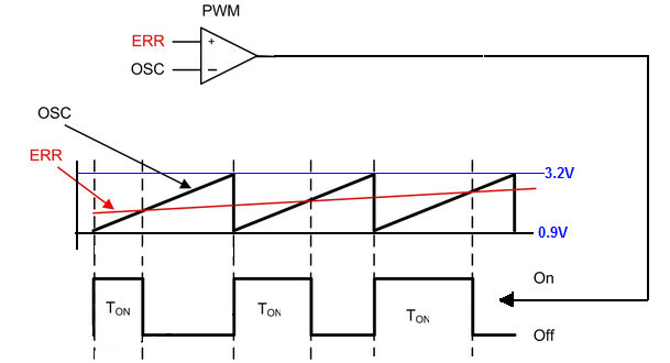
This diagram explains everything you need to know.

enter image description here

As you can see we have a comparator and two signals at the input.

At noninverting we apply the "error" voltage and at the inverting input, we apply sawtooth waveform from the internal/external oscillator.

And by changing the voltage at noninverting input we can change the duration of the output pulse. Notice that when the value of the input "error" signal is greater than that of the sawtooth wave, the output of the comparator is high. Otherwise, the output of the comparator is low.

SG3525 has the internal sawtooth oscillator. And you can set the oscillator frequency by choosing corresponding values for RT and Ct capacitor. And the output waveform from the oscillator is "send" to PWM comparator.

This sawtooth wave swings between 0.9V and 3.2V.

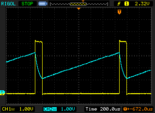
This is how voltage across the Ct capacitor (pin 5) and OSC output (pin 4) looks like in working circuit.

enter image description here

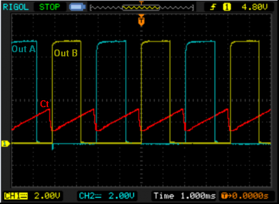
And here you have the voltage across Ct capacitor and two outputs. The Pin 11 (Out A) and Pin 14 (Out B).

enter image description here

enter image description here

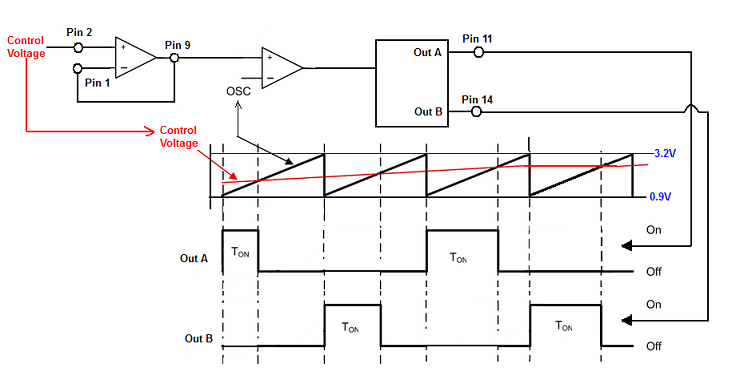
The "error" signal can be applied directly to pin 9 or if you want to use the additional opamp to pin 2. But in this case, you need to connect pin 1 together with pin 9.

And kept in mind that the voltage at this pins shouldn't be larger than 5V.

Here you can find example diagram http://www.twovolt.com/wp-content/uploads/2016/07/DC-MOTOR-SPEED-CONTROLLER-1.pdf

\$\endgroup\$
6
  • \$\begingroup\$ Wow, that explains a lot! Thank you very much. One more question. What exactly is the output of pin 9? \$\endgroup\$
    – Joris
    Commented Feb 14, 2018 at 16:56
  • \$\begingroup\$ pin 9 is a PWM comparator input (Error signal) in my diagram. \$\endgroup\$
    – G36
    Commented Feb 14, 2018 at 16:58
  • \$\begingroup\$ Maybe I expressed myself incorrectly. The output of pin 9 is fed into pin 1, right? But what does the signal coming out of pin 9 look like? \$\endgroup\$
    – Joris
    Commented Feb 14, 2018 at 17:05
  • \$\begingroup\$ The pin 9 is the input for PWM comparator and also the output of error amplifier. And if we connect pin 1 to pin 9 the error amplifier will work as a voltage follower. The voltage at pin 9 will look like the voltage at pin 2. And voltage at pin 2 is a DC voltage which has an effect on PWM. \$\endgroup\$
    – G36
    Commented Feb 14, 2018 at 17:25
  • \$\begingroup\$ Sorry, I missed the top left part of the last diagram. It's still not 100% clear to me how that part works, due to my lack of basic understanding I guess, but I'll try figuring it out now. Thanks again for your time. \$\endgroup\$
    – Joris
    Commented Feb 14, 2018 at 20:20
4
\$\begingroup\$

They are basically a throttle control; normally you're trying to hit some target like an output voltage or a motor speed. If you're off that target, a voltage or speed sensor connected to that "error amplifier" lets the PWM controller know, so it adjusts PWM until that error is 0 (you're on target).

Compensation is the art of controlling the frequency response of that error amplifier to prevent overshoots and oscillation.

That's the outline; now you either have to learn a lot about control systems theory, feedback amplifiers, and stability, or follow one of the example designs very closely.

A simple approach for experiments would be to connect an adjustable voltage into pin 2, and simply short pins 1 and 9 turning the "error amplifier" into a unity gain buffer. Then you should be able to see the duty cycle change as you adjust the voltage on pin 2.

\$\endgroup\$
4
  • \$\begingroup\$ Why is it necessary to have an adjustable voltage on pin 2? Is there an inherent lack of precision in this IC so you need to finetune somehow what you have set up with the resistor and the capacitor when defining the frequency and the dead time? What would happen if I just connect the same voltage as the input voltage to pin 2? \$\endgroup\$
    – Joris
    Commented Feb 14, 2018 at 15:03
  • \$\begingroup\$ I am unclear what you are asking : pin 2 IS the input voltage. If you want to modulate (vary) the pulse width, you do that by varying that input voltage. RT/CT setup the PWM frequency; R(pin7) sets the dead time between switches (to prevent them both being ON at once), that input voltage controls the PWM duty cycle. \$\endgroup\$
    – user16324
    Commented Feb 14, 2018 at 16:00
  • \$\begingroup\$ If pin 2 is the input voltage, what is pin 13 then? \$\endgroup\$
    – Joris
    Commented Feb 14, 2018 at 16:47
  • \$\begingroup\$ As it's a modulator, it has 2 inputs. Pin 2 controls the pulse width, pin 13 controls the pulse amplitude (or supplies the gate voltage of the power switches) \$\endgroup\$
    – user16324
    Commented Feb 14, 2018 at 16:55

Your Answer

By clicking “Post Your Answer”, you agree to our terms of service and acknowledge you have read our privacy policy.

Not the answer you're looking for? Browse other questions tagged or ask your own question.