Given that it looks like an car project I'd guess that by LED you means an indicator lamp with built-in series resistor.

simulate this circuit – Schematic created using CircuitLab
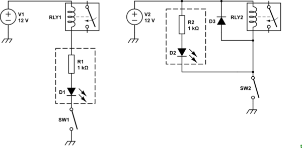
Figure 1. (Left) What you've done. (Right) what you need to do.
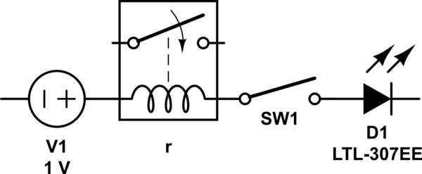
If there is a series resistor in the LED it will limit the current through the circuit to about 10 or 12 mA. This won't be enough to energise your relay and if you measure the voltage across the relay you probably only have a volt or so.
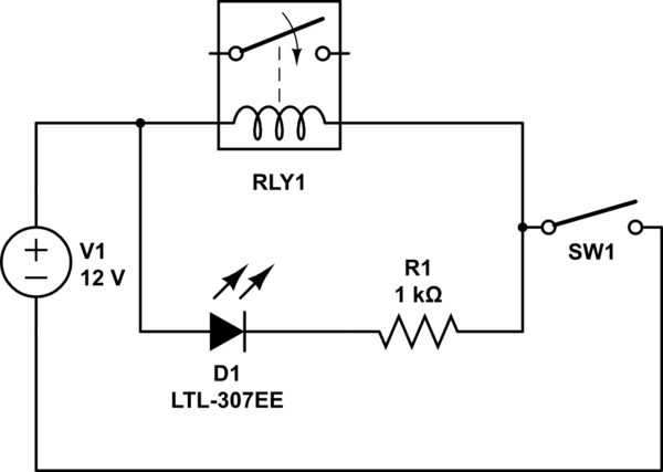
Instead, wire the indicator in parallel with the relay. Relays give an inductive reverse-voltage "kick" when switched off and this is enough to blow the LED. Unless you know that either the relay or the indicator has protection built in then add D3 to protect the indicator LED.
Finally, note the use of the ground or chassis symbols in my schematic and omitted from yours. You have no return path for the current so, as drawn, neither the relay or LED would work. The schematics above have a ground return and so complete the loop to allow current to flow.


