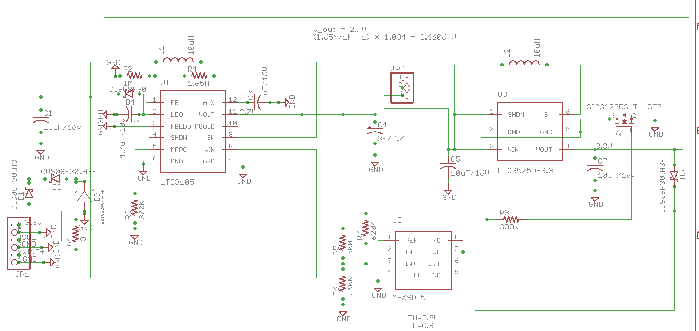
I've created a dual source energy harvesting board to store energy from small energy sources, like a 3V 15mA solar panel, into a 3F 2.7V supercap and to power a small wireless node (3.3V, 30mA), but I am having trouble with the mosfet.
Schematic is below:
 The voltage regulator LTC3125 (U1) gets the energy from the solar panel and steps the voltage up to 2.65V to charge the 3F 2.7V supercap.
The supercap is the input for the 3.3V voltage stepup regulator LTC3525D-3.3 (U3) and its output (3.3V) goes to the load (wireless node).
This regulator should get cut from the circuit when the voltage of the supercap goes below 0.9V and be reconnected if the supercap goes above 2.5V. This is done by the non-inverting op-amp with additional hystheresis, the MAX9015 (U2), that drives a low side N-Mosfet SI2312BDS-T1-GE3 (Q1).
The op-amp is powered by two sources: if the sun shines, it is powered by the 2.1V regulated voltage from the LTC3105 (LDO, pin2). If no sun and supercap >0.9V, the power comes from the LTC3525D-3.3 output. If no sun and supercap <=0.9, then the opamp is off and so is the mosfet. Usually the supercap is >1V.
My problem is, that even in best conditions, the LTC3525 does not turn on.
Here my test:
instead of solar panel I used a power supply 3V@70mA
no load on 3.3V output
I let the supercap charge from 0.2V. The supercap goes to the multimeter with 60cm (1.96ft) cables to measure current. Current is about 35mA going to the supercap.
when supercap reaches 2.5V, the mosfet turns on
Supercap voltage starts to drop quickly, discharge current from supercap is 40mA, instead of few uA.
While the supercap was discharing, I measured: Supercap: 2.3V. Op-Amp: OUT = 2.1V. Mosfet: V_GS=2.1V; V_DS=0V; V_GD= -2.1. LTC3525: V_IN = 2.3V; V_OUT=2.1V. LTC3525: LDO=2.1V, V_OUT=2.65V
Supercap kept discharing until about 1.78V, then LDO of LTC325 started to drop to 1.8V and op-amp turned off (min V_IN = 1.8V). I don't know why LDO dropped, the power supply was still on.
The LTC3525 seems not to start. The 2.1V on its V_OUT comes from the LDO, not from it.
The mosfet can conduct 4A with 2.1 V_GS and R_DS=0.03 ohm.
Older version of the board that had no mosfet work correctly.
I had to use a mosfet to disconnect the LTC3525 and its load, because it tented to oscillate around the SHDN when starting while supercap at 0.7V: If the supercap was charging from 0V, at 0.7V (SHDN threshold of LTC3525) the LTC3525 would start, drop the supercap voltage to 0.65V, the LTC3525 shutdowns, supercap goes to 0.7V and so on… even with bigger (330uF) cap on V_IN of LTC3525 same problem.
To prevent this, I though, a mosfet could cut the LTC3525 completely until the supercap is at 2.5V. At this voltage, the LTC3525 can start safely without oscillating around its SHDN threshold voltage.
I am not sure why the LCT3525 does not work, maybe are the mosfet connections wrong?
All the caps are very close (1mm or less) to their depending IC, except the supercap, as already explained.
The components have been used before already, except the mosfet.
I've already removed and resoldered the LTC3525, to be sure the connections were ok.
Any idea?
Thanks in advance for your help
Sincerely
