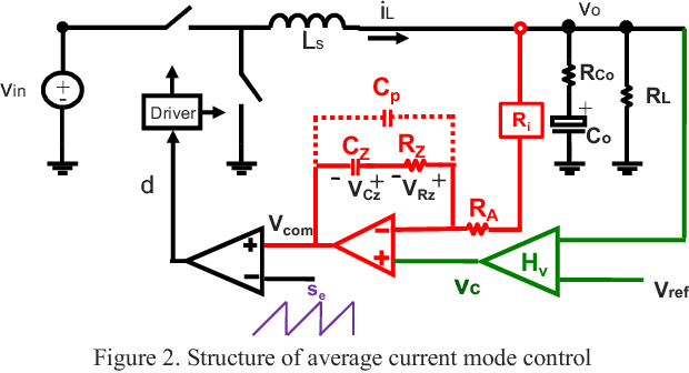
This is the structure of average current mode control (source here).
Please look at signal \$V_{com}\$ at the positive input of PWM modulator. For proper operation, in steady state the magnitude of \$V_{com}\$ should be in range peak to peak of ramp signal. Is there a clear procedure (almost like step by step) to guarantee this?
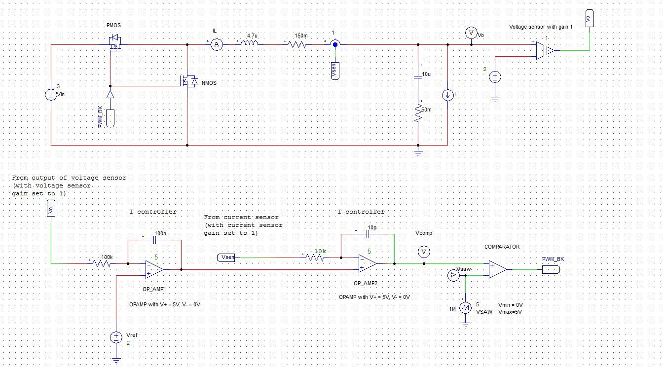
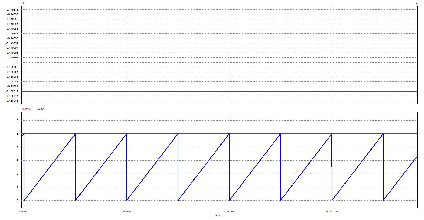
I tried to simulate this and even using simple integral compensation but \$V_{com}\$ is always out of range of ramp signal.
This is my simulation result with target 3V input and 2V output.


