1
\$\begingroup\$

I'm using the LPV821 op-amp (http://www.ti.com/lit/ds/symlink/lpv821.pdf) for a buffer circuit (voltage follower). Below is my circuit, where the desired output has the same voltage as the input (V2):

enter image description here

The circuit works only with ideal source (little or no impedance between V2 and non-inverting pin). But it does not output anything for my non-ideal voltage source (When there's a large resistor between V2 and non-inverting). I was wondering if I could have some suggestions on why I'm not getting the desired output.

NOTE:

1- The V+ - V- supplies for this op-amp cannot be more than 4V.

2- This circuit works as expected with LM741 op-amp. The only difference is that I removed R12 because LM741 needs higher supplies.

UPDATE:

Below are my observations in order to figure out the problem:

1- When I connect the positive (1.4V) and negative (-1.4V) supplies to the op-amp and disconnect the other pins, all the pins are at 0V.

2- When I connect an ideal source (no R10), ALL the pins have the same voltage as the input (V2).

3- When I add the R10 (700KOhm), the output goes to zero. I also measured the voltage at the non-inverting pin and it's at zero, even though the input (V2) was not zero.

4- When I paralleled a 100K with R10 the output was almost like input: a sine wave with minor drop in the amplitude.

5- When I replaced R10 with a 200KOhm resistor, the output was substantially attenuated but not zero.

From 3,4, and 5, I can conclude that the current in the non-inverting pin is pretty high and this current causes a voltage drop across the R10. I don't know why this happens. Maybe the op-amp is damaged?

\$\endgroup\$
7
  • \$\begingroup\$ What is the frequency of the input? \$\endgroup\$
    – τεκ
    Commented Apr 7, 2018 at 0:56
  • \$\begingroup\$ The input freq is 60Hz \$\endgroup\$
    – vmontazeri
    Commented Apr 7, 2018 at 0:57
  • \$\begingroup\$ Why that chip? If it’s because of the 17V supply, there are alternatives. \$\endgroup\$ Commented Apr 7, 2018 at 4:31
  • \$\begingroup\$ What's the load on the output? \$\endgroup\$
    – The Photon
    Commented Apr 7, 2018 at 5:02
  • 1
    \$\begingroup\$ How about power supply decoupling capacitors? \$\endgroup\$
    – Andy aka
    Commented Apr 7, 2018 at 9:13

2 Answers 2

1
\$\begingroup\$

Per problem description, all indications are that the input impedance of the tested circuit is fairly low, under 100 kOhm or less. Which isn't expected, since the input leakages and offsets for the LPV821 are of the order of 10 pA, which should translate into about 100 GOhm effective input impedance.

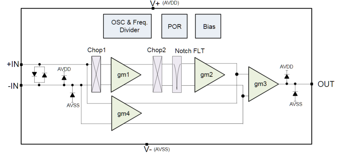
However, the LPV821 is a very delicate precision "chopper" amplifier, nanopower:

enter image description here

The datasheet is full of notes on how to protect pins from overvoltage or overcurrent. Having accidentally only 4 V can damage the IC. Given questionable design of power rails in this question, I would say that this test sample is permanently damaged.

\$\endgroup\$
4
  • \$\begingroup\$ Thanks. How should I modify the power supply to avoid overvoltage/overcurrent? Beside adding the bypass caps around R13 and R14? \$\endgroup\$
    – vmontazeri
    Commented Apr 7, 2018 at 2:24
  • 1
    \$\begingroup\$ @user1512681 Use some Zeners at least. \$\endgroup\$ Commented Apr 7, 2018 at 2:25
  • \$\begingroup\$ Zeners across R13/R14? Or simply replace the resistors with zeners? \$\endgroup\$
    – vmontazeri
    Commented Apr 7, 2018 at 2:28
  • \$\begingroup\$ @user1512681, replace or across, doesn't matter. But if you are concerned with overall power consumption, you need more accurate selection, depending on your power source and load value. \$\endgroup\$ Commented Apr 7, 2018 at 2:36
0
\$\begingroup\$

I see a huge problem. Remove the 20K R12 that is in series with the power supply. You cannot expect the opamp to work with its supply rail choked off with a huge resistor like that. The opamp is made to connect directly to the power supply.

If your intention for that resistor was to find a way to lower the power supply voltage to a range compatible with the opamp I would strongly suggest finding a voltage regulator solution to reduce the voltage to the proper range. The 20K resistor is unable to regulate. The voltage drop across it will change with each change of current through it.

\$\endgroup\$
4
  • 1
    \$\begingroup\$ I believe OP is doing this to achieve the low supply voltage for his tests. Doing this though, he would need to add adequate decoupling. There are better ways to reduce Vsupply! \$\endgroup\$
    – AlmostDone
    Commented Apr 7, 2018 at 0:42
  • \$\begingroup\$ @Michael, this is a 3.6 Max amplifier, with 1 uA total current. You can't feed it at 17V. A pair of 1uF bypass caps must be there however. \$\endgroup\$ Commented Apr 7, 2018 at 0:42
  • \$\begingroup\$ 1uF bypass caps would completely defeat this application, however something is needed, since PSRR starts to drop off around 2kHz. Probably 10 nF would do. \$\endgroup\$
    – τεκ
    Commented Apr 7, 2018 at 0:50
  • \$\begingroup\$ @τεκ, I mean the caps across R13 and R14, power supply. \$\endgroup\$ Commented Apr 7, 2018 at 2:01

Your Answer

By clicking “Post Your Answer”, you agree to our terms of service and acknowledge you have read our privacy policy.

Not the answer you're looking for? Browse other questions tagged or ask your own question.