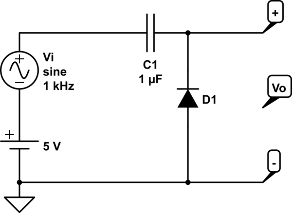
Because of C1 the DC on the left side can be ignored. It will make no difference1 if the 5 V DC supply is there or not.
1 If there is DC present then C1 must be rated for the DC voltage and if it is a polarised capacitor such as an electrolytic it must be inserted in the correct orientation.
- Without D1 the output voltage will be a sine wave with the same amplitude as the input but swinging positive and negative.
- With D1 inserted the output will be "clamped" or limited to 0 V if it tries to go negative. Your question shows that you understand that there will be a 0.7 V drop across the diode if significant current is flowing. Therefore Vo will be clamped to -0.7 V when the input goes negative.
- Once we go past the bottom of the input sinewave the input voltage is increasing from \$ V_{pk-} \$ to \$ V_{pk+} \$. The right side of C1 will rise with this and so will go to \$ V_{pk+} - V_{pk-} - 0.7\ \text V = 2V_{pk} - 0.7 \ \text V\$. Note that the 5 V makes no difference.

Figure 1. Running your circuit with Vi = 5 V AC on top of 5 V DC we get the results above.
- The left side of C1 reaches +10 V.
- The right side of C1 reaches +5 V (because that is how much AC we have seen up until now).
- At point three the left side of C1 is back where it started.
- After this point the AC is clamped at -0.7 V and so it will rise to \$ 2V_{pk} - 0.7 \ \text V \$.
Your English is fine!


