0
\$\begingroup\$

I'm trying to use a 555 timer to create a variable frequency from a resistance, the output frequency should be about 1 kHz up to 300 kHz. I'm using a TS555CN CMOS version, which can oscillate up to 2.7 MHz or so.

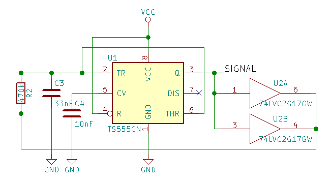
Circuit diagram

When using different values for R2, I see a linear relationship between the output frequency (measured using a scope) and 1/R2 for larger values of R1, but the frequency goes up less than expected for resistances below about 1k, and this effect gets progressively worse as the resistor values go lower, down to 10Ω where the frequency is just 1/3 of the expected frequency.

I've wired the 555 using the output as control, this as I need a 50% duty cycle. In earlier tests I noticed that, especially at lower resistor values, the duty cycle goes up more and more until it's about 70% and the output was far from a square block wave. This is of course an effect of the output not going to Vcc (3.3V for me), plus the internal resistance of the output. To solve this I put a non-inverting buffer on the output (U2 - actually two of them, as it's a dual package). That solved the duty cycle problem, and I'm getting perfect 50% square wave at all resistor values.

When trying the same with a ceramic cap instead of a film cap I got a less precise result (expected) but the linear part continued down to 470Ω, before the frequency really started to lag.

Changing the capacitor from 33 nF to 10 nF didn't make a change. The frequency itself of course changed, but the effect on linearity was the same, implying it has to do with the current. But here it ends... I don't understand why, as at 1k the peak charge current is no more than about 2 mA, while the buffers can supply some 20 mA each. Disconnecting one of the buffers did not make a difference.

(edit for additional info) The purpose of this circuit is to measure the resistance of a liquid - so the resistance is a given, and can not be changed. This will have to go down to about 50Ω...

\$\endgroup\$
2
  • \$\begingroup\$ Put the output voltage of the 74LVC2G17 gates on the output of your scope and check if the low/high voltages stay the same at low and high values of R2. \$\endgroup\$ Commented Apr 10, 2018 at 10:04
  • \$\begingroup\$ There is a slight drop in voltage (0.2-0.3V) with R2 = 47Ω, and a more serious drop at R2 = 10Ω (just over 2V between high and low level; Vcc = 3.3V). At higher values for R2 I don't measure any drop. Pretty much within expectation based on the rated output current of this buffer. \$\endgroup\$
    – Wouter
    Commented Apr 10, 2018 at 14:35

2 Answers 2

2
\$\begingroup\$

The peak current is 2/3 the supply voltage divided by the R2 + the output resistance of the buffers. With 1K and a 3V supply voltage that would be less than 2mA.

I suggest you make the capacitor maybe 100x less, so something like 330pF NP0 ceramic. You want the minimum resistor to be much more than the output resistance of the buffer for linearity. There will also be some nonlinearity as a result of the propagation delays in the buffer and 555. At 1kHz you will need about 2M for the resistor which is still within reason for a CMOS 555.

This will also help deal with the duty cycle issue as the duty cycle will be less dependent on the symmetry of the output resistance of the buffer. Often CMOS outputs are much better at sinking current than sourcing it (if not, the designer has placed significantly larger p-channel than n-channel transistors). In the case of the 74LVC2G17, there are hints in the datasheet that the internal resistance when sourcing is about 25-30% higher than when sinking.


You have added the requirement that the resistor cannot be increased, in which case I would suggest a fast MOSFET driver and a couple of smallish SOT-23 ~5A MOSFETs instead of the buffer. Good bypassing will be very important.

You could alternatively consider a fixed resistor in series with the changing resistor, which will make it even more nonlinear, but in a quite predictable way (easy to subtract out if you are doing a measurement with a microcontroller).

\$\endgroup\$
3
  • \$\begingroup\$ Based on a voltage of 2/3 Vcc = 2.2V, and the rated current delivery of 24 mA, my charge resistance should be able to go down to 46Ω with the two combined. Yet I see serious non-linearity at 10x that already. Some further analyses showed an internal resistance of about 20Ω, which sounds quite reasonable. I couldn't find any hard numbers in the data sheet, just absolute maximum source/sink ratings of 100 mA. \$\endgroup\$
    – Wouter
    Commented Apr 10, 2018 at 13:56
  • \$\begingroup\$ Resistor can't be increased in value: that's the very parameter I'm trying to measure through the output frequency. \$\endgroup\$
    – Wouter
    Commented Apr 10, 2018 at 13:57
  • \$\begingroup\$ I was thinking in line of the MOSFET drivers already, but in the end the buffer does the job. Thanks for the suggestions. \$\endgroup\$
    – Wouter
    Commented Apr 10, 2018 at 16:26
1
\$\begingroup\$

Solved the problem. It was indeed the internal resistance of the buffers that did it.

I rebuilt the circuit - now with 1 µF ceramic + 22 µF electrolytic as decoupling right at the 555 for extra stability - and tested again, now with different capacitors (15 nF and 2x 6.8 nF film caps) and a range of resistors from 10Ω up to 2k and some larger values.

I was able to calculate the measured frequency to within about 1% error (the tolerance of the resistors used) by making two corrections:

1) I had to adjust the capacitance of the caps upward by about 1 nF - I suppose this is due to stray capacitance of the solderless breadboard and all components, plus the 5% tolerance of those caps,

2) I had to increase the resistor value by 31Ω. The latter obviously to compensate for the internal resistance of the buffers (meaning each one has about 62Ω internal resistance).

In the end I found a linear relation between (R2 + 31) and the measured frequency.

Of interest is also that I did not notice a significant difference in high and low time, also not at high frequencies, though at those frequencies the waveform was far from square. Must be at least in part due to all the stray capacitance of the breadboard. The next step is to connect this indeed to a microprocessor for frequency measurement.

Thanks all for replying, and confirming some of my thoughts. That does give the motivation to try again and again and come to a good conclusion.

\$\endgroup\$
2
  • \$\begingroup\$ The internal resistance of the buffers won't be particularly stable with temperature, nor with supply voltage, but maybe good enough for whatever you are aiming for. \$\endgroup\$ Commented Apr 10, 2018 at 16:42
  • \$\begingroup\$ Supply voltage will be stable - using a regulator. Temperature not so much, expecting 5-35°C as typical temperatures. Lots of testing to be done :-) And the MOSFET option is always a good backup plan. \$\endgroup\$
    – Wouter
    Commented Apr 10, 2018 at 16:58

Your Answer

By clicking “Post Your Answer”, you agree to our terms of service and acknowledge you have read our privacy policy.

Not the answer you're looking for? Browse other questions tagged or ask your own question.