0
\$\begingroup\$

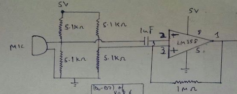
I had this task of converting the output of a microphone's voltage (data-sheet link attached) to a range of 0-5V, as this is the range required for the input to an ADC chip.

While I know that op amps generally are used for this task, I couldn't find a comprehensive working mechanism for the circuit - the resistors, the capacitor, etc.

Could someone please explain to me what actually happens in this circuit, and what would the gain of the op amp finally be?

From the datasheet, I calculated the maximum voltage (V max) of the microphone to be 8.9 mV. (10^(-41/20))=8.9mV, where -41 is the sensitivity.

Datasheet of mic: http://docs-europe.electrocomponents.com/webdocs/0f2a/0900766b80f2a57c.pdf

This is a part of the circuit which is supposed to amplify the mic output voltage to a range of 0-5V

\$\endgroup\$
1
  • \$\begingroup\$ have you built this circuit? is it stable? You have positive feedback on the 358. On your other questions the capacitor is acting as a high pass filter, the 5.1k resistors are used to bias your op amp, i.e. supply its reference voltage(virtual earth) using a simple potential divider 2.5V in your case. \$\endgroup\$
    – IC_Eng
    Commented Apr 11, 2018 at 10:38

2 Answers 2

1
\$\begingroup\$

More than likely, the microphone has an output impedance that is high (drain of a JFET = current source) and so the two 5.1 kohm resistors (that connect to the microphone and bias it) form the effective input resistor to the inverting input. If you analysed the circuit you'd realize that the two 5k1 resistors are to be regarded as in parallel (for AC analysis) so the effective input resistance is about 2.5 kohm.

So the small signal AC gain is 1 M / 2.5 k = 400.

This will be the gain up to about 2 kHz then the op-amp (LM358) will be unable to sustain this gain at higher frequencies and you have a roll-off in gain of 6 dB/octave.

\$\endgroup\$
0
\$\begingroup\$

There are two issues here.

First the voltage you supply to the microphone seems to low. There are two 5k resistors one to ground and one to 5V, the equivalent circuit is a 2.5V supply through a 2.5k resistor. Since the current consumption is rated to 0.5mA the voltage on the equivalent series resistor is 1.25V leaving only 1.25V for the microphone , under the standard operating voltage of 1.5 specified.

Second, the 1nF capacitor seems to low, with 2k2 microphone impedance gives a 72.343 kHz cutoff frequency, way to high for audio applications, maybe you mean 1 microfarad?

The overall impedance is 2.2k microphone impedance parallel to 2.5k supply resistor impedance = 1.17kohm. With 1uF the gain is 1Mohm/1.17kohm = 854

The microphone is given as -41dBV for 1Pa ( very loud, like near a speaker at a concert) that means ~10mV output. Rail to rail the OA can output 2.5V/1.41 = 1.7V . Divided with the gain of 854 will be 2 mV which means -13dB that is a bit louder than a vacuum cleaner for maximum OA output.

\$\endgroup\$

Your Answer

By clicking “Post Your Answer”, you agree to our terms of service and acknowledge you have read our privacy policy.

Not the answer you're looking for? Browse other questions tagged or ask your own question.