3
\$\begingroup\$

I have a Carson Reflex Wheel remote control for my RC car. It has two potentiometers, one for accelerating and one for steering.

My goal is to control the RC Car from my PC by sending commands via the serial connection to the arduino.

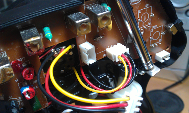
I would like to unplug the potentiometers and put the pins (in the white box -> see image) on two Arduino pins so the Arduino can control the remote control. This would exclude the potentiometers from the circuit and make the arduino kind of replace them.

The remote control operates at 12V.

enter image description here

The two potentiometers are connected with the black red yellow wires.

What circuit do I have to use between the pins (in the white box -> see picture) of the remote control and the Arduino?

UPDATE: I recently got a multimeter. The voltage between the yellow and black pins is 5V (constant). Between the other pins there is no voltage unless the potmeter is connected. In this case the voltage between black and red varies from -4.9 (left), -2.9 (center) to -0.4 (right). Between red and yellow it's 0 (left), -2 (center) and -4.4 (right). (depending on the position of the steering wheel)

\$\endgroup\$
5
  • \$\begingroup\$ What would be the purpose of that modification? What's the Arduino to do with it? \$\endgroup\$
    – stevenvh
    Commented Jul 31, 2012 at 14:29
  • 1
    \$\begingroup\$ Oli notes that this is an over 6 Mpixel image. Next time would you please scale it down to maximum 630 pixels wide? (That's the width it shows in most browsers) \$\endgroup\$
    – stevenvh
    Commented Jul 31, 2012 at 14:38
  • \$\begingroup\$ The purpose would be something like controlling the rc car with the pc or phone. Sorry about the image. \$\endgroup\$
    – Toast
    Commented Jul 31, 2012 at 14:46
  • 1
    \$\begingroup\$ I scaled it down for you. It's now 96 % smaller. Yet I don't see any loss in information. If you think the original image may reveal extra details, post the smaller one, and link to the original. \$\endgroup\$
    – stevenvh
    Commented Jul 31, 2012 at 14:49
  • \$\begingroup\$ Do you have a schematic for the controller? Can you trace out the circuit that connects to the pots by looking at the board? I'm trying to get a feel for what kind of circuit these pots are wired up to, so we can figure out how to control it from electrical outputs. \$\endgroup\$
    – drxzcl
    Commented Jul 31, 2012 at 14:54

4 Answers 4

5
\$\begingroup\$

If you want to control the car from the PC via the Arduino you'll have to setup the serial port to receive the commands and output a PWM signal to emulate the potmeters.

I'm not really an Arduino man, but your code should look a bit like this. It receives + and - commands from the PC and increases or decreases the virtual potmeter position. Note that this is just a framework; there's no testing for minimum or maximum position, for instance.

const int analogOutPin = 9; // Analog output pin that the LED is attached to

int outputValue = 0;        // value output to the PWM (analog out)

void setup() {
  // initialize serial communications at 9600 bps:
  Serial.begin(9600);
}

void loop() {
  if ( Serial.available()) {
    char ch = Serial.read();

    switch(ch) {
      case '+':
        outputValue+;
        break;
      case '-':
        outputValue-;
        break;
    }
  }

  // change the analog out value:
  analogWrite(analogOutPin, outputValue);   
}

Filter the output signal with an RC filter. This will give you a voltage between 0 V and 5 V. Measure the voltage range of the potmeters and report back. It's possible that you'll have to amplify the signal.

edit after the updated info in the question
Nice! So the potmeters give you an output range from 0 V to 5 V, which is exactly what the Arduino's output will do as well. So you can use the analogWrite function like in the example code above. Note that the Arduino guys call it "analog", but the AVR doesn't have an analog output, so it's probably just PWM. The Arduino doesn't have an RC-filter to make it DC, so you'll have to add the resistor and capacitor yourself.

enter image description here

A value of 100 kΩ for the resistor, and 1 µF for the capacitor are probably OK.

edit after your measurements and comment
The arrows on the RC filter schematic indicate a voltage. The arrowhead points to the signal whose value you want to measure, the back end of the arrow to the reference you're measuring against, which is usually ground. So if you would connect the ground pin of a scope's probe to the lower connection, and the probe's tip to \$V_{IN}\$ you'd see the Arduino's PWM output. Probe at \$V_{OUT}\$ and the PWM will be averaged to a DC voltage with some ripple. That's what we want if we want to emulate the potmeters.

If I understand correctly the black and yellow wires carry the potmeters' values, and are referenced to the red wire, which is +5 V. (This is confusing; black is generally accepted to be ground!). You can look for ground on the PCB, but we can use the +5 V reference too, we'll just have to flip the filter upside down:

enter image description here

The top line is your red wire. \$V_{IN}\$ is the output from the Arduino, you have two of those. \$V_{OUT}\$ for one of those goes to the black wire, the other output to the yellow one.
\$\endgroup\$
8
  • \$\begingroup\$ "It's possible that you'll have to amplify the signal." That is exactly what my question is about. How can I measure the range of the potmeters? I don't have a multimeter. I replaced the potmeter of the control with the another one that has the caption "B10k". It makes the car steer from right to left in the last (or first) two percent of the range of my potmeter. \$\endgroup\$
    – Toast
    Commented Jul 31, 2012 at 15:53
  • \$\begingroup\$ The potmeter resistance is not going to help us. If there's 9 V across it then the halfway position will give 4.5 V, whether it's the current 10 k potmeter or a 100 k. Without multimeter it may be hard, but it's worth trying: can you trace the voltage from your battery to the potmeters? If we're lucky the potmeter works directly with the battery's voltage. If not you'll have to borrow a multimeter somewhere, or better buy one. I've seen prices as low as 8 euro for a basic model, it will always come handy. \$\endgroup\$
    – stevenvh
    Commented Jul 31, 2012 at 15:59
  • \$\begingroup\$ I bought one ;). I put the measured values in the question. \$\endgroup\$
    – Toast
    Commented Aug 6, 2012 at 13:21
  • \$\begingroup\$ What do the arrows with Vin and Vout mean (sorry for this noob question)? Do I have to connect it to the red or yellow pin? Maybe I'm wrong but it seems like the black one is ground and the yellow one is Vcc here. \$\endgroup\$
    – Toast
    Commented Aug 9, 2012 at 19:34
  • \$\begingroup\$ @Toast - Updated my answer. Can you confirm that the negative voltages on the black and yellow wires are measured with the black probe (negative) of your multimeter, and the red probe (positive) to your red wire? \$\endgroup\$
    – stevenvh
    Commented Aug 10, 2012 at 7:12
4
\$\begingroup\$

edit
This answer builds on the question's phrase "unplug the potentiometers and put them on two Arduino pins". Apparently OP wants it the other way around. Read my other answer for that.
(end of edit)

If you would want to control the car from your PC then the Arduino's circuit is simple. Connect the two potmeters to two of Arduino's analog inputs, where you connect the potmeters' ends to ground and +5 V resp.

Next use the USB connection as a virtual COM port to send the ADC readings to the PC.

void setup()
{
  Serial.begin(9600);                  // set up Serial library at 9600 bps
}

void loop()
{  
  Serial.println("Data:");             // sync 
  Serial.println(analogRead(0), DEC);  // read ADC channel 0 and send to PC as decimal
  Serial.println(analogRead(1), DEC);  // same for channel 1
  delay(100);                          // wait 100 ms before sending next readings
}
\$\endgroup\$
9
  • \$\begingroup\$ It doesn't seem like the answer is finished. Accidental submit? \$\endgroup\$
    – drxzcl
    Commented Jul 31, 2012 at 15:04
  • \$\begingroup\$ @drxzcl - I don't know. What's missing? \$\endgroup\$
    – stevenvh
    Commented Jul 31, 2012 at 15:05
  • \$\begingroup\$ I thought the asker wanted to actually control the car through the arduino, not log the controls. Or am I misunderstanding your answer? \$\endgroup\$
    – drxzcl
    Commented Jul 31, 2012 at 15:08
  • 2
    \$\begingroup\$ To control the car, wouldn't you want to "write the potmeters" (assuming such a phrase makes sense) of the remote instead of reading them? \$\endgroup\$
    – drxzcl
    Commented Jul 31, 2012 at 15:12
  • 1
    \$\begingroup\$ @drxzcl - " unplug the potentiometers and put them on two Arduino pins so the Arduino can control the remote control." That's what my answer gives a solution for. Again, if he means something else he simply has to say so, but IMO that's what he's asking. I can't read it in any other way. \$\endgroup\$
    – stevenvh
    Commented Jul 31, 2012 at 15:17
2
\$\begingroup\$

You are reading the analog vales which the potentiometers are giving you, so you want your Arduino to read them and then you can write the code to do whatever you want with the data. Do make sure that you are wiring the Arduino's analog pins directly to the pots, and not some other point on the circuit board of your controller (if you want the raw results, which I think is what you are looking for).

Steven's code is correct.

\$\endgroup\$
2
\$\begingroup\$

Most proportional RC sets, excepting PCM sets (which on HF/VHF tended to be more expensive - they are common on 2.4 GHz, but that is not a 2.4 GHz antenna) use a chain of pulse width modulated pulses to signal the channel positions.

If you can find this signal, perhaps between the encoder IC and the actual transmitter circuit, injecting a PWM output from the Arduino there would be ideal.

\$\endgroup\$

Your Answer

By clicking “Post Your Answer”, you agree to our terms of service and acknowledge you have read our privacy policy.

Not the answer you're looking for? Browse other questions tagged or ask your own question.