1
\$\begingroup\$

I'm moving away from project boards for the first time and was looking to get a bit of feedback before I send my PCB design into production. I'll preface this by saying that the design itself has been prototyped and is working, and that portions of the design came from the assembler games forums, though I've made some additions and tweaks.

Anyways, I'm building a Dreamcast RGBs and 480i/480p switcher for myself and a few friends who're interested in one. I'm pretty happy with its current state and I just need to ask a couple of questions before it's finalised.

Images of the PCB Design Option 1 (One Ground Plane)

Images of PCB Option 2 (Two Ground Planes)

My PCB is has two layers and the bottom layer of it is a solid dedicated ground plane. I'm fairly certain it's adequate, though I want to be sure. I've not dealt with using planes before.

The top layer of the PCB contains all of the traces and components. My R, G, B and Left and Right audio lines are fairly sensitive, given analogue video and analogue unbalanced audio. I've spaced the traces generously (upwards of 15 times the traces width in some spots for video signals) but the top of my PCB currently has no copper fill. Will not having the spaces between my analogue traces filled or via shielded lead to interference concerns? I've also heard of boards becoming warped if one side is filled and the other isn't. Is this true?

Off-topic, but for my decoupling capacitors I have three vias on each ground pad going to the ground plane. I was reading a Texas Instruments document that mentioned to do this. Given that inductance is reduced in parallel, is this a good design choice?

Lastly, if I did fill the top layer, the video and audio traces run along the length of the board (my spacing is to minimize cross-talk and parasitic capacitance, due to running these traces in parallel) and the video traces each have a 220µF capacitor in series. The combination of the spaces between the capacitors and the parallel traces would create ground loops and I'm unsure of a way around it. Given my spacing I'm unsure of whether or not I would see a large benefit of having a ground plane on the top layer. Any pointers are appreciated.

In case it matters, Vsync is at 60Hz, while Hsync will be at either 15.75kHz or 31kHz, depending on the SPDT switch position. I don't believe the audio lines will exceed 44.1kHz and RGB lines should peak at around 14Mhz. It's a low frequency circuit, overall. My power and ground traces are 20 mils and data lines are 10 mils. I don't expect current much over 50mA - 100mA. My +5V source is from the multi out on the Dreamcast which itself comes from the power supply 5V rail.

That was a lot. Thanks to anybody who read that and has suggestions.

\$\endgroup\$

2 Answers 2

1
\$\begingroup\$

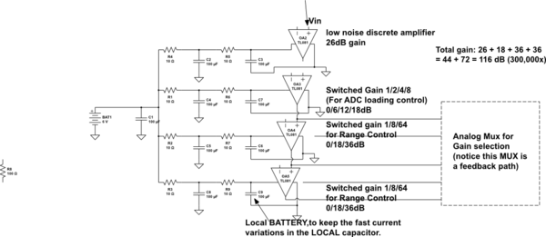
As a kid, I built numerous multi-stage bipolar AC-coupled low-frequency amplifiers..................that oscillated. Eventually, I learned to avoid that fun putt-putt-putt-putt of motorboating oscillators (caused by the shared internal impedance of 9 volt batteries); the key concept is "local batteries", achieved with R_C_R_C_R_C_R_C networks to isolate the high frequency current surges.

Imagine a circuit with 10 amplifiers, and 10 bypass capacitors, each capacitor installed 1mm (one millimeter) away from the VDD pin of each amplifier.

Run a heavy wide VDD trace all over the board. And have a GND plane underneath.

What happens? Any current demand by any of the amplifiers will cause a VDD sag all over the PCB within a few nanoseconds. This sharing of the VDD is the path to oscillation, and to trashed video/audio circuits.

How to prevent this sharing, this upset of settling to final values, this potential oscillation? Use some isolating resistors.

FORM A VDD TREE.

Using this concept, I build a rather broadband amplifier, gain of 600,000 or 116 dB, Flow of 50KHz and Fupper of 200KHz. There was no oscillation.

schematic

simulate this circuit – Schematic created using CircuitLab

There will be DC interactions in the GROUND plane. This particular amplifier was quite high passband --- 50Khz to 200KHz --- and with at least one DC_block RC in each stage, the DC-feedback by GND PLANE was seeing 4+ zeros (anti-pole) of attenuation.

\$\endgroup\$
5
  • \$\begingroup\$ I'm not sure if I follow you correctly. Are you suggesting that I use a series resistor along with a parallel capacitor for my voltage line? I've not heard the term "isolating resistor" before in my studies or research. \$\endgroup\$ Commented Apr 21, 2018 at 11:05
  • \$\begingroup\$ Yes. Use a low-value series resistor, if you can. Without resistors, any demand anywhere will cause a immediate and global sag in VDD; with finite Power Supply Rejection by the amplifiers, all the stages will interact. \$\endgroup\$ Commented Apr 22, 2018 at 2:35
  • \$\begingroup\$ And these low-value resistors 1-10 ohms, are excellent dampening resistors. The inductance of the VDD wiring, and the VDD capacitors, are guaranteed to resonate. Without some dampening, the VDD response has peaks. Pick Rdampen = sqrt(L / C) or bigger. \$\endgroup\$ Commented Apr 22, 2018 at 2:37
  • \$\begingroup\$ I've got some more questions, if you don't mind. First, I've added a second Imgur gallery to my post where I've added a ground plane on the top my of circuit. I'm not good at tracing return paths yet, would you be able to tell me if the vias will properly "merge" the two ground planes, or will I have looping issues? Would I be better off with the single ground plane for this circuit? I'm worried about interference on the video and audio traces. \$\endgroup\$ Commented Apr 22, 2018 at 10:21
  • \$\begingroup\$ Next, since I don't have any inductors in my circuit, would I need to add one in order to utilize the resistor? Where would the best location for the resistor to be? Right when the voltage comes in from the Dreamcast on the PCB, or just before the IC? The unit is internally powered, I forgot to mention. Would it be best for me to add a new capacitor in parallel with the resistor, or just use my existing 10µF? My audio and video lines are supplied by the Dreamcast and don't actually interact with my voltage line at all. They're only on the circuit for passthrough and video coupling. \$\endgroup\$ Commented Apr 22, 2018 at 10:28
0
\$\begingroup\$

If you take 5V from the presumably noisy Dreamcast supply, I second analogsystems' recommendation of adding a low value resistor like a few ohms in series with the 5V input. You can also add a footprint for an electrolytic cap, you have enough space and footprints are free.

A 74HCT86 could be a better option than a 74LS86.

Also you could get crosstalk between your RGB signals, not from the traces themselves which are properly spaced, but from the three electrolytic capacitors that are quite closely spaced. Caps bodies are conductive so if they are close together there can be parasitic capacitance between them.

If the signals come in on a 75R coax, you can route your trace with an impedance of 75R.

There is only one GND pad on both sides. If the RGB and Sync signals use coax cables, each will have its own shield. The simplest solution is to just remove the soldermask on the back of the board and solder each coax shield there.

\$\endgroup\$

Your Answer

By clicking “Post Your Answer”, you agree to our terms of service and acknowledge you have read our privacy policy.

Not the answer you're looking for? Browse other questions tagged or ask your own question.