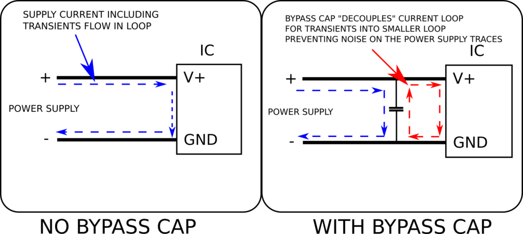
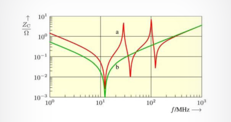
From what I've read online, for SMT components there should be traces from VCC/GND pins to the capacitor and then vias to the ground and power planes.
The situation is a bit different for through-hole boards, because the VCC and GND pins will be directly connected to the ground and power planes. In this situation, are traces to the decoupling capacitor even needed? Can the decoupling capacitor not be placed close to the chip and simply connected to the planes with vias?


DerStrom8's approach but it's too black magicky for me and ultimately requires a lot more effort in CAD than simply placing the capacitor close to the chip and dropping some vias from it. \$\endgroup\$