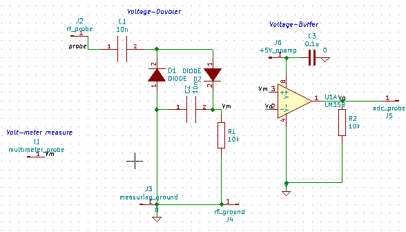
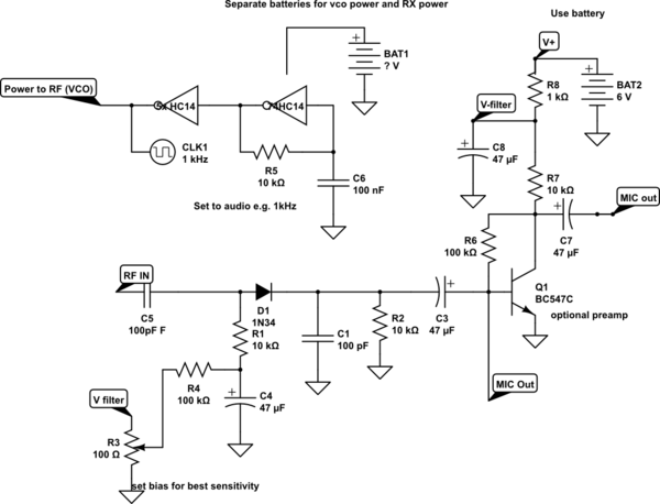
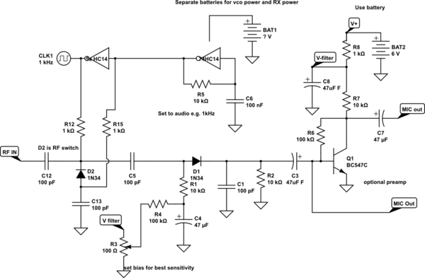
I want to measure voltage across a T-line to visualize standing waves on the line.
something like this video min 6:53 and this experiment Measuring Standing Waves on a Microstrip Transmission Line
I have purchased this VCO to generate RF source signal.It's 5mW.
I am using 12V 5A power supply.
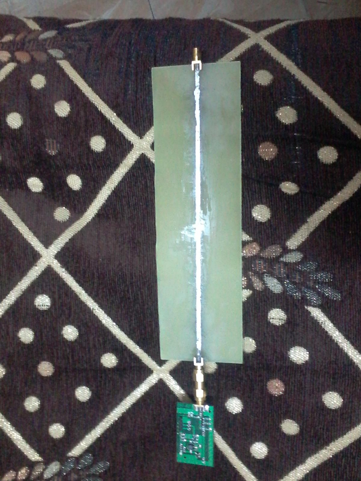
This is my circuit (T-line is open as I want to meassure open, short, and, matched)
Then I used a voltage multiplier circuit to detect the RF signal(also tried half wave rectifier) and connected it's output to my analog voltameter with 0.5V, 0.25V, 100uA scale, but I didn't get any reading.
I used 1n34a diodes with ceramic 10nF caps.
Questions:
- Why doesn't voltmeter read any value?
- What is the dominant factor that would cause that?
- How to diagnose the circuit without expensive equipments?
- Is there any easy to find device to get high power RF(from cellphone, TV, ...)?
Note:
- I used solder on the microstrip, because I am planing to put a stepper and slide the probe through the line(similiar to slotted line device).
- I don't use lecher line as it would require more powerful RF source.
- I have designed a circuit to generate around 2Ghz, but I delayed the fabrication to verify the concept with the above VCO.
- I know that it is more practical to use microstrip wave guide with ground plane, but it would be hard to get these small vias connecting upper plane with the lower one and It would take a long time to arrive.
I want the minimum setup(just working).
Thanks in advance.
UPDATE:
I have tried it and it's working as expected"I havn't soldered buffer port yet".
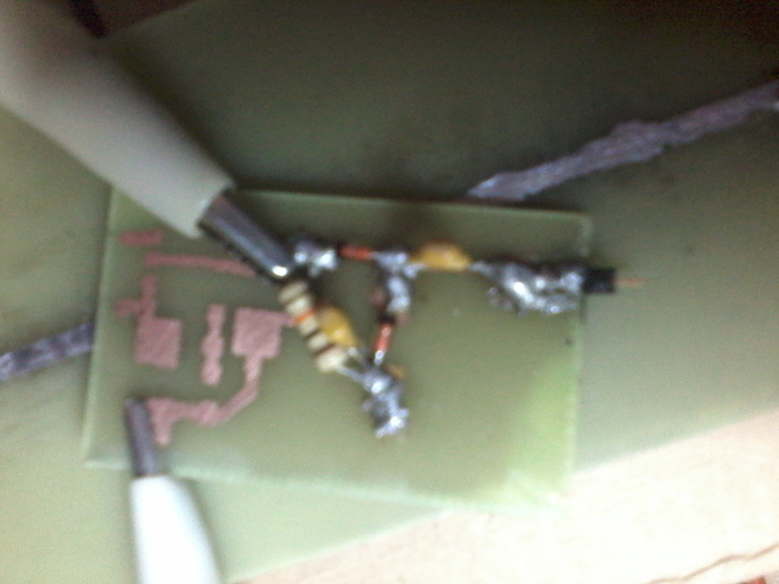
My short circuit is not perfect and it is lowering the maximum amplitude.
@The Photon: thanks a bunch.

