Short version: How do I make an analog multiplier that takes two analog DC inputs?
Long version:
I made a comment recommending Ben Eaters videos for another question, while doing so I ended up watching some myself (again) and thinking to myself "hmmm... I wonder if it would be easier to make some parts purely analog".
The bus could be just one wire where different voltage levels would later be translated to bits with an ADC.
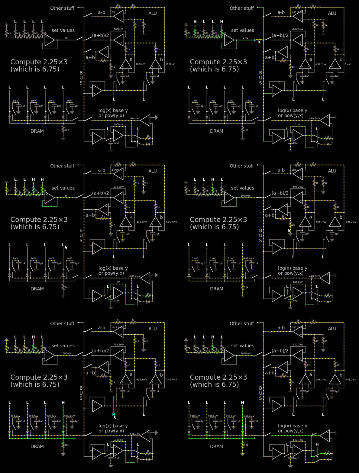
Just messing around a bit I came this far which theoretically can calculate the Fibonacci numbers:
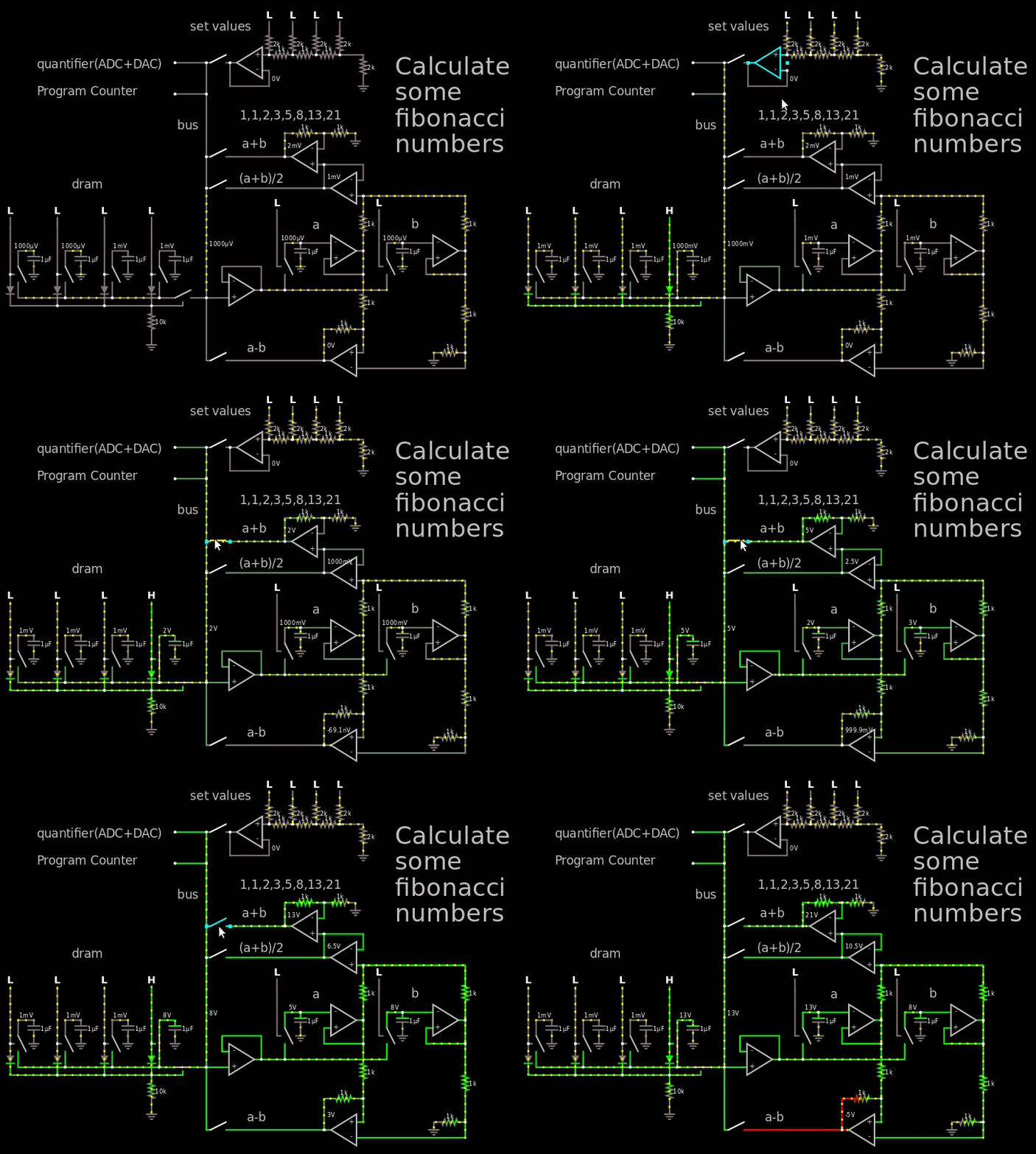
Figure 1, small demo of hybrid computer calculating the first fibonacci numbers
Link to simulator.
In the gif above I go way out of the voltage range so it's easy to see the fibonacci numbers, in reality I would just use the 250 mV = binary 1 (the LSB at the "set values") and then let it propagate through the DRAM which holds 4 bits per capacitor.
The important part to look at in the gif is the output of the op-amp to the right of the "a+b" text, it shows the Fibonacci numbers.
In between every operation I would quantify the answer by using an ADC followed by a DAC. So if I would read 1.1V then the DAC would turn it into a 1.0 V which afterwards would be stored in the DRAM. And then once every X clock the entire DRAM would have to go through the quantizer to make sure the capacitor doesn't float away.
The ALU is only able to do +, - and average. I was thinking about making the multiplication and came to a halt. I've made and seen diode based multipliers before, but I don't want to use them because the diodes has to be matched. I rather use resistors that I can trim with a potentiometer. Anywhoo, I came up with a hybrid multiplier, half analog, half digital.
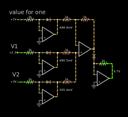
So I made a first with identical resistors everywhere.
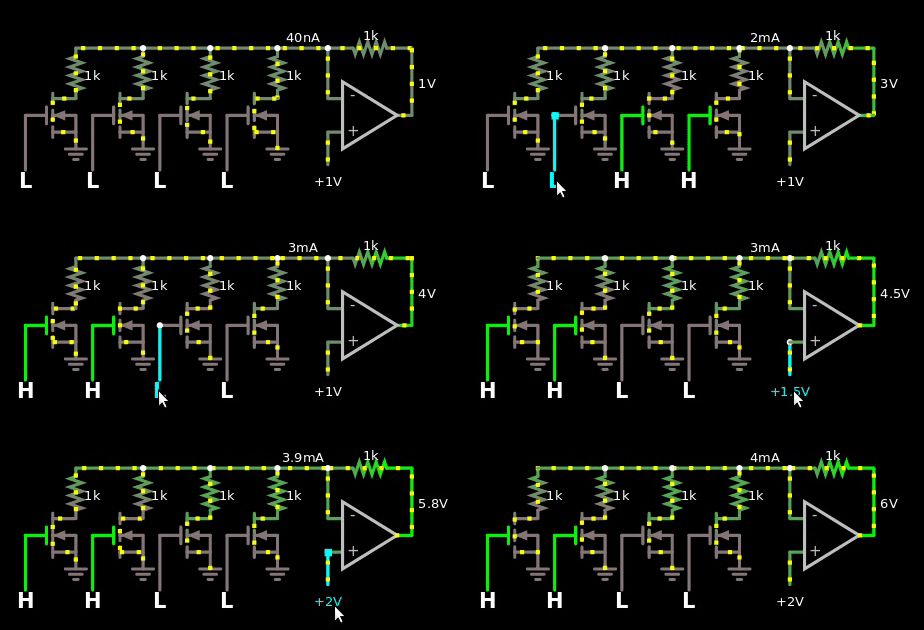
Figure 2, naive multiplier between digital numbers and analog values. The digital value is offset by 1.
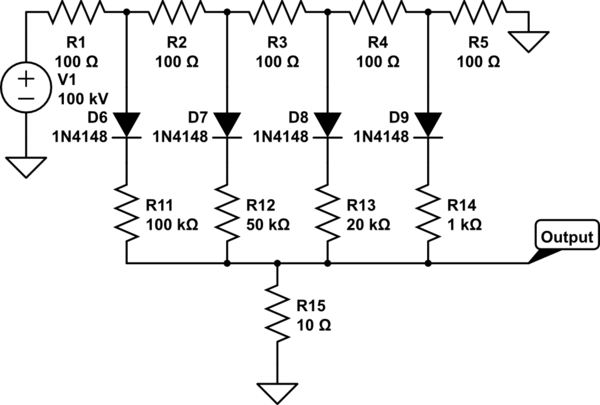
Which I then turned into this with binary weights:
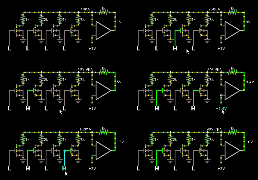
Figure 3, naive multiplier between binary weighted digital numbers and analog values. The digital value is offset by 1.
This reminded me of R2/R ladders, but I couldn't make them work with the op-amp.
However, I thought about how R2/R ladders worked, and I remembered that their output is multiplied by their voltage source. So I finally came up with this design:

Figure 4, R2/R based multiplier between binary weighted digital numbers and analog values
I do like it, the only problem however is that the bus is analog, just one wire. So if I'm forced to use the solution in figure 4 above, then I'm forced to use another ADC at the multiplication area of the hybrid CPU. I can't reuse the one at the quantizer area.
Time for the question:
How should I make a multiplier that takes two analog inputs?
- I do not want the solution that is based on 3 diodes that and 4 op-amps because you can't trim diodes. My belief is that if they are mismatched then they will give an answer that is off by more than 250 mV. I have not tried this in the real world.
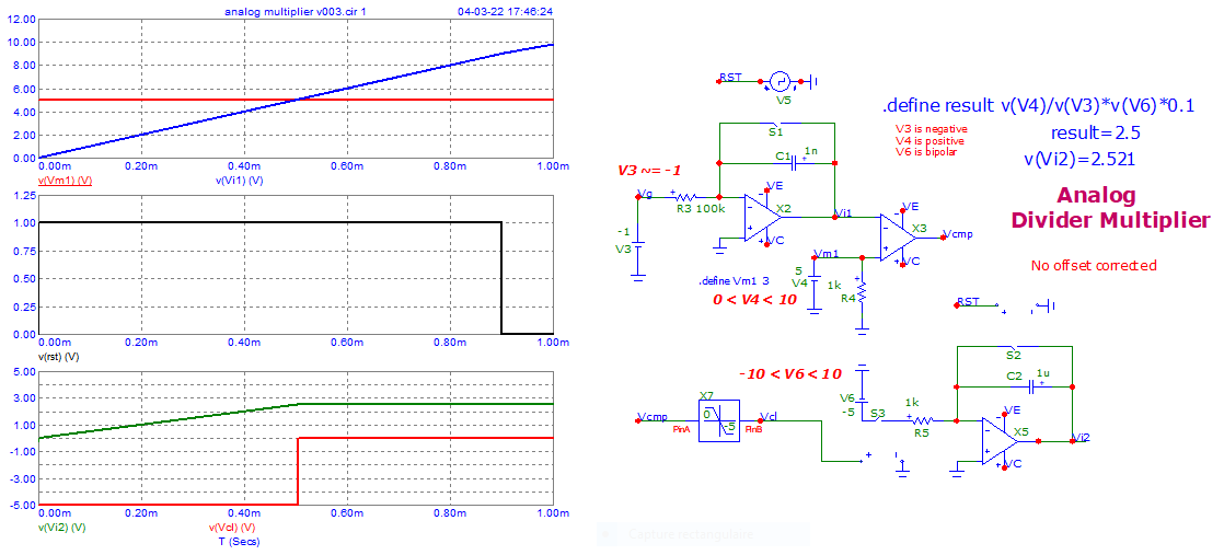
- I have tried the MOS based multiplier in the link literally an inch above this word, but I don't know if I'm dumb. I can't get it to work in the simulator. See gif below for failure of MOS implementation. Or click this link for the simulation.
- I do not want to throw a microcontroller at the problem.
- I do not want to use a motor that rotates and uses some shenanigans.
- I was thinking about using a RC filter in a lowpass formation to get hold of the \$e^{\frac{-t}{RC}}\$, charge and discharge and use a ramp + measure the time it takes for the capacitor to reach some value. It's the same idea as with the diode, it's just much much slower, not that I really care. Though I can use a resistor to trim the RC constant. I would prefer not using this solution because it feels... like I'm solving it in the wrong way.
- The precision doesn't have to be perfect, right now it's just 4 bits per capacitor, this gives each level \$\frac{4}{2^4}=0.25\$ V if VDD is 4 V. Though in the future, it would be fun to store 8 bits per capacitor.
- After the multiplication has been done, it will be taken to the quantizer to make sure the value is as close to a binary value as possible. So small errors are okay.
Here's the gif that shows my failure trying to make the MOS based one:
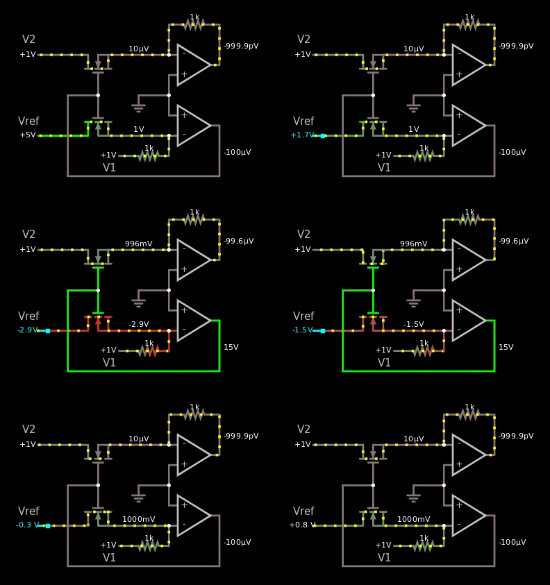
Figure 5, I copied the schematic from the wiki link above, yet it doesn't work in the simulator.
If it would have worked, then I should have seen the value 1 V somewhere as I changed the voltage of the reference from 5 V to -5 V.


