9
\$\begingroup\$

I have two questions...

  1. I have seen that different value capacitors in an amplifier circuit, sound different... For example, an amplifier circuit with a 470uf capacitor, has more bass, and treble... A 1000uf capacitor, has a uniform distribution of frequencies more or less... A 330uf capacitor sounds like it has more focus on the vocals... mid range...

So, what is the real reason for them to sound the way they do? In physics or mechanics or electronics sense...

  1. In an electric guitar and amplifier setup... Introducing a resistor value, between the amp and the guitar, changes the way the guitar sounds... I have tried lots of values, some of them are, 330k, 470k and others in that range... Why does this setup, act like equalizers? The resistor i connect is in the positive terminals, not ground ones...

This seems to work in a cd player to music system too... The resistors become like presets of music equalizers...

I understand we are changing the impedance, but why do they sound so different at different impedances...?

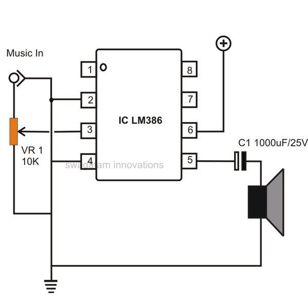
Example Circuit:

enter image description here

\$\endgroup\$
17
  • 7
    \$\begingroup\$ Have you measured this effect, or is it purely from experience? Remember, the human brain is very good at finding patterns where there are none. \$\endgroup\$
    – Hearth
    Commented May 10, 2018 at 13:35
  • 1
    \$\begingroup\$ If all caps were the same, they would have only allowed, or rejected, more frequencies, there would have been the same sound for two same valued caps. In practise, there is also a matter of electrolytes, methods of manufacture, age, parasitics, that add up to make, sometimes, even same capacitors "sound" different. \$\endgroup\$ Commented May 10, 2018 at 13:35
  • 4
    \$\begingroup\$ Where is this capacitor located? A filter? Power supply? Just resting on top? \$\endgroup\$
    – Colin
    Commented May 10, 2018 at 13:45
  • 1
    \$\begingroup\$ Do you get a measurable difference in the amplifier output? How big of a difference? Does it affect specific harmonics? Does it add a new resonance where there wasn't one otherwise? And where are the capacitors located, anyway? Is this a power supply bypass capacitor, or an integrator feedback capacitor, or what? \$\endgroup\$
    – Hearth
    Commented May 10, 2018 at 13:49
  • 1
    \$\begingroup\$ In that position it is part of a filter, the cutoff frequency changes with capacitance. \$\endgroup\$
    – Colin
    Commented May 10, 2018 at 13:52

6 Answers 6

11
\$\begingroup\$

The impedance (think of it as resistance) of a capacitor changes with the frequency of the signal passing through. The lower the frequency (bass sounds) the higher the impedance.

The impedance of the capacitor also depends on its value. A capacitor with a higher value will have a lower impedance than a capacitor with a lower value. For the same frequency, a small valued capacitor represents more resistance than the large value capacitor.

In order to get more bass, you have to use a larger capacitor in series with the speaker.

C1 in your circuit is there to block DC from the amplifier. At DC, a capacitor is very close to an open circuit - DC cannot pass.

The change over is gradual, however. The capacitor doesn't just block DC. It also impedes the flow of other frequencies. The lower the frequency, the more it is blocked.

At some point it is no longer noticeable. For working with filters (the capacitor/speaker combination is a high pass filter,) this point is defined as the point where the amplitude is reduced by half (that's -3dB.)

I'm not going to get into calculating the cutoff of a filter - there's plenty of explanations on the web that go into much more detail than I want to.

For the other side (resistor changes sound,) we have to look at inductors.

The pickups on your guitar are inductors - basically just coils of wire.

Inductors are the opposite of capacitors. Inductors let DC pass just fine, but their impedance goes up the higher the frequency. It also goes up as the value of the inductor increases.

You aren't changing the impedance of the inductor (pickup.)

When you change the resistor at the amplifier, you are changing the load on the inductor.

A resistor that is connected across the inductor forms a voltage divider. How the voltage is divided between the pickup and the resistor depends on the frequency of the signal - the impedance of the inductor changes with frequency which changes how the voltage is split between the inductor and resistor.

The combination of the coil and the resistor forms a low pass filter. It removes high frequencies.

The point (frequency) where this begins to be noticeable depends on the resistor loading the coil. A higher value resistor allows more high frequencies to pass. Lowering the value of the resistor lowers the frequency at which you can hear a difference.

Another thing that will happen is that the resistor also changes the amplitude of the signal presented to the amplifier. A higher resistor means less signal getting to the amplifier, which results in a quieter output.

A lower resistance means more signal to the amplifier, which gives a louder output.

For a guitar player, there is also the interesting possibility of distortion. You provide so much of an input signal that producing the amplified signal would require more voltage than the power supply of the amplifier.

When that happens, the output voltage will "stick" to the powersupply voltage until the input signal is smaller.

This is known as clipping, and is a bad thing in a general amplifier, but can be a useful thing for a guitar player.
\$\endgroup\$
8
  • \$\begingroup\$ Wow... That is great knowledge to me... I didn't know most of it, and i am sure it comes with years of experience... Thank you very much... I have learnt something from you today... \$\endgroup\$
    – user188171
    Commented May 10, 2018 at 14:39
  • \$\begingroup\$ A question, so when the frequency to the capacitor changes, the impedance changes, in this case, what is the observable output in the circuit... As the impedance changes... Frequency i think is the frequency of the audio, am i correct, or is it the voltage frequency... \$\endgroup\$
    – user188171
    Commented May 10, 2018 at 14:42
  • 1
    \$\begingroup\$ That is a very simplified explanation of things that there are whole books about. If any of the answers helped you, consider upvoting. \$\endgroup\$
    – JRE
    Commented May 10, 2018 at 15:36
  • 1
    \$\begingroup\$ @Vibhu a simple high-pass filter would be to put a small cap in series with a speaker; high frequencies "see" a lower impedance in the cap while lower frequencies "see" a higher impedance, so only (well mostly) the higher frequencies get through to the speaker. Similarly, a capacitor in parallel effectively shunts the higher frequencies away from the speaker, while for the lower frequencies the speaker has a much lower effective impedance than the cap so they go through it and you get a low pass filter. Mind you it's very crude and not recommended :) \$\endgroup\$
    – Doktor J
    Commented May 11, 2018 at 14:25
  • 1
    \$\begingroup\$ @Vibhu unless doing it as a short-term experiment just to see the effects... mind you, when doing the parallel option I would suggest putting a small resistor (maybe half the rating of the speaker, so 4𝝮 for an 8𝝮 speaker) so you're not creating a near-dead-short for high frequencies, which might damage your sound source. \$\endgroup\$
    – Doktor J
    Commented May 11, 2018 at 14:27
4
\$\begingroup\$

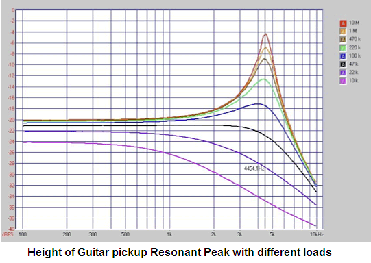
The inductance of an electric guitar pickup resonates with the capacitance of the cable feeding the amplifier. If the impedance of the amplifier is very high (a vacuum tube or FET) then the resonance produces a high frequency peak in the frequency response. If the impedance of the amplifier input is low then the resonance peak is damped so there is a loss of high frequencies. A guitar speaker does not have a tweeter to produce high frequencies so the resonant peak is used instead.

Here is a graph of the height of the peak with different amplifier input impedances:enter image description here

\$\endgroup\$
3
  • \$\begingroup\$ Is it as simple as just connecting a resistor in series with the amplifier/pickup to change its impedance, and have a similar resonant peak...? Good informational chart there... \$\endgroup\$
    – user188171
    Commented May 11, 2018 at 2:07
  • \$\begingroup\$ To put some numbers to this, I measured a Fender Stratocaster pickup a couple of years ago. DC resistance around 8K Ohms: inductance 3.8 Henries; and no I do not mean mH or uH. \$\endgroup\$
    – user207421
    Commented May 13, 2018 at 22:13
  • \$\begingroup\$ Hi - This image appears to come from another website. Please edit your answer and add a reference to comply with site rules and reduce the risk of plagiarism claims. Thanks :-) (If you ping me in a comment using "@SamGibson" after adding the reference, then I'll remove this comment to reduce clutter.) \$\endgroup\$
    – SamGibson
    Commented May 28, 2018 at 2:38
3
\$\begingroup\$

Guitars are a bit of a funny source, as the transducer has a high (and generally highly inductive) output impedance.

What this means is that it is highly sensitive to capacitive loading and it does not take much to put a resonance in the audio band.

Adding series resistance changes the Q of any such resonances and thus changes the tone.

You would probably find that the additional series resistance makes more difference at the guitar end of the cable then at the amp end (where the cable capacitance cannot be isolated) and that it again makes more difference to a guitar which has its on body volume control cranked (Less shunt resistance so the Q is higher again).

You cannot think of a guitar pickup as being a classical voltage source, they are way too far removed from that for the voltage source in series with a resistor model of an audio source to apply.

Now as to the electrolytic caps in an amp, it depends very much on which ones we are discussing, the DC block in a feedback network (or on the gain control of an instrumentation style mic amp for example) will make noticeable changes, mainly to the low frequency corner position, while a coupling cap (provided it is large enough to avoid signal voltage being developed across it) is usually fairly non critical.

I would warn that when working on audio, the ear is a purely crap tool for comparisons, seriously, how you hear things one day to the next (especially once you have been working on things for a few hours) is just so variable. You must listen obviously, but understanding what you hear comes from measurement, fortunately this is easier and cheaper then it has ever been, get a decent PC soundcard and some measurement software, job done.

As to your speaker coupling cap, speakers have a rather variable impedance, and this interacts with the cap to change the frequency response, speakers are generally not pure resistors in reality, so the usual approach is just to make the cap huge so that any interactions are below the audio band, 1000uF is good for most full range things.

\$\endgroup\$
2
  • \$\begingroup\$ I haven't checked for difference between guitar end and amplifier end, i used two cables, with the resistors in between, so they were equally long in cable measurement... Thank you, that all is quite new to me... I recall Q from Star Trek however... I have to familiarise myself with input and output impedance in a practical way... \$\endgroup\$
    – user188171
    Commented May 10, 2018 at 14:19
  • \$\begingroup\$ Simply speaking, i think we maybe processing recurring events differently... And much more when it comes to sound (than visuals) \$\endgroup\$
    – user188171
    Commented May 10, 2018 at 14:28
1
\$\begingroup\$

Because you are modifying the frequencies in your circuit. A pass band filter could be converted into a high pass (or a too high cutoff frequency filter) just changing a capacitor or a resistance (cutoff = 1/2*piRC). Actually that is how a speaker works, the treble is a high pass filter, bass is a low pass filter, and the middle is a pass band filter, these different frequencies will generate different sounds. How easy is to listen the sound? It depends on your circuit, the amplifiers (I am talking about the signal, lets say voltage), how easily it can transmit (or amplify) the vibrations (in terms of the mechanical design), etc

\$\endgroup\$
1
  • \$\begingroup\$ That is very intriguing... Thank you for the explanation, i got most of it ... The equation is new to me, thanks.. \$\endgroup\$
    – user188171
    Commented May 10, 2018 at 13:56
1
\$\begingroup\$

Walt Jung and Bob Pease have shown there are sonic or waveform differences in capacitors. Some research papers conclude the difference is the ability to squeeze the dielectric as voltages change, that squeezing causing a reduced spacing between plates and a related increase in capacitance.

Thus glass and air and some plastic capacitors contribute minimal sonic changes.

\$\endgroup\$
2
  • \$\begingroup\$ There is a whole breed of capacitors that store energy in mechanical deformation of a piezoelectric material. They achieve higher capacitance in a smaller package that pure electrostatic devices. But they probably are not so great at RF. \$\endgroup\$ Commented May 10, 2018 at 18:33
  • \$\begingroup\$ Interesting facts... \$\endgroup\$
    – user188171
    Commented May 11, 2018 at 2:18
0
\$\begingroup\$

JRE has a pretty good answer. Resistors are linear in response across frequencies. Capacitors and inductors change impedance as frequency changes. Capacitors pass lower frequencies and conductors pass lower frequencies. The combination creates a filter of various frequencies. A network of various components will determine not only the frequency of resonance, but its harmonics, which are the behavior at intervals such as half or double the frequency. A clean sine wave in a simple Capacitor or Inductor circuit will have an easy response to visualize. What needs to be taken into account is the source impedance, load impedance, and the network you are adding. Keep in mind none of your components are perfect. Amplifiers, both pre and power do not have a linear frequency response. Things like heat and quality of materials also tend to make things less linear. Im not a guitar guy, but I get the electronics. If you are interested in creating your own sounding instrument, try building a bridge network. They can be extremely sensitive. If you wanted to get creative, you could even put some active components into a bridge.

\$\endgroup\$
3
  • 1
    \$\begingroup\$ Sorry... Capacitors pass HIGHER freq... \$\endgroup\$
    – bmr
    Commented May 10, 2018 at 20:17
  • \$\begingroup\$ 'Inductors', not 'conductors'. There is no such thing as a harmonic at half the frequency. Amplifiers and preamplifiers that don't have not only linear but flat frequency response within the passband are exhibiting a serious fault, unless they lack a GNFB loop. \$\endgroup\$
    – user207421
    Commented May 11, 2018 at 0:31
  • \$\begingroup\$ I could only find information as to how to bridge an amplifer, that is make it a mono unit... \$\endgroup\$
    – user188171
    Commented May 11, 2018 at 2:02

Your Answer

By clicking “Post Your Answer”, you agree to our terms of service and acknowledge you have read our privacy policy.