I am doing a hobby project working with a ATMega328, however, I am struggling with a with a small issue when I am trying to drive the output high on multiple pins at once. Somewhat new to this field, I am not 100% sure where to start debug.
The problem so far is. I have set up my arduino to program an ATMega using the internal clock. I have then uploaded my program using the arduino IDE to the uC. So far, everything looks good. The program itself is basically just setting some pins to output, and then high.
After this I move the uC to my breadboard, and measure the voltage on the output pins, and everything is dandy. All the output pins shows roughly 4.7V.
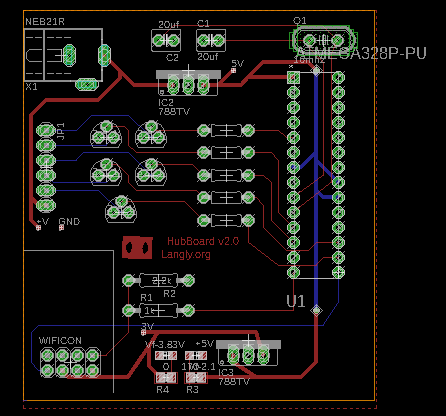
Now, I move the uC to my PCB ( I can upload the board and schematics somewhere if it helps ), but now when I measure the voltage on the pins, I see 0.120 or so volts on the same output pins.
Measuring the voltage coming in on the Vcc pins, I can see that it's well within the acceptable range. Somewhere around 4.9V.
Also, after some debugging, I have found that if I only enable ~2 pins, I can get the expected ~4V. However, if I enable 3+ output pins, I see the voltage drop.
I am somewhat confused, and new to this topic, so all suggestion would be useful. There seems to be something different between my PCB and breadboard configuration, and I am struggling a bit to debug where it goes wrong.
- Edit:
The code for this is simple:
 void setup() {
  // put your setup code here, to run once:
  //pinMode(10, OUTPUT);
  //pinMode(8, OUTPUT);
  pinMode(3, OUTPUT);
  pinMode(5, OUTPUT);
  pinMode(6, OUTPUT);
  pinMode(10, OUTPUT);
  pinMode(11, OUTPUT);


  //digitalWrite(8,HIGH);
  //digitalWrite(10,HIGH);
  digitalWrite(3, HIGH);
  digitalWrite(5, HIGH);
  digitalWrite(6, HIGH);
  digitalWrite(10, HIGH);
  digitalWrite(11, HIGH);

}

void loop() {
  // put your main code here, to run repeatedly:

}
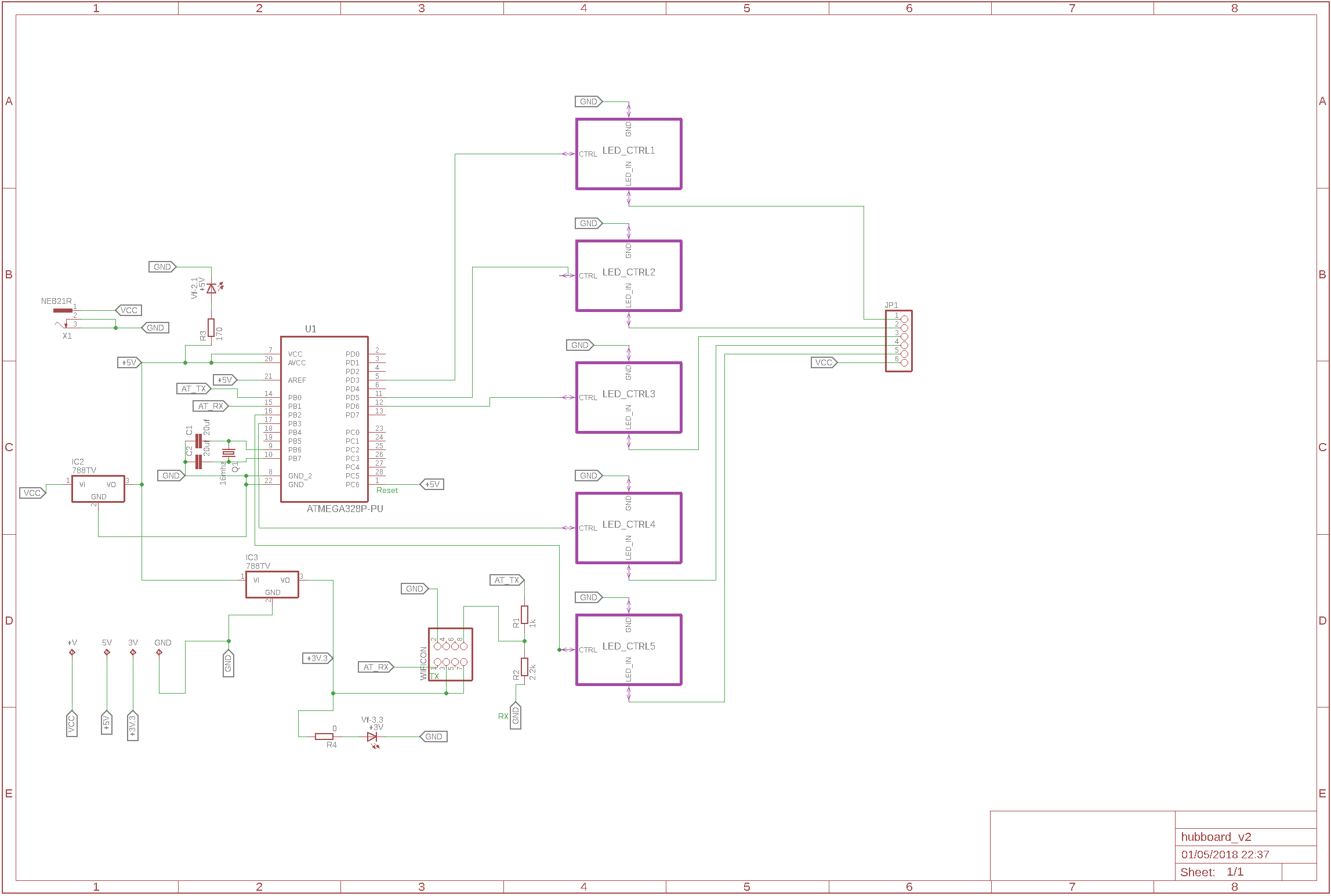
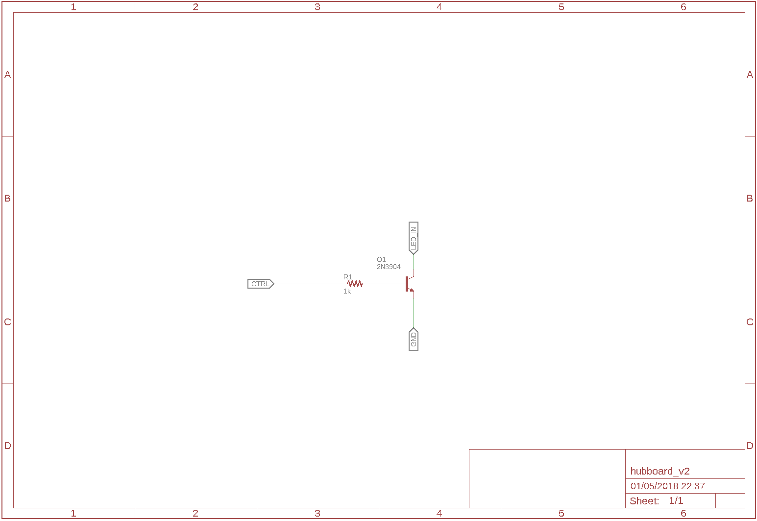
For the schematics
The toplevel view; For now ignore the leds and the clocks. Not connected in the current version


