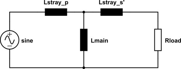
Please see the ideal transformer equivalent circuit.

simulate this circuit – Schematic created using CircuitLab
There are no losses, our ideal transformer is only inductances. As the stray inductances do nothing but store energy in the magnetic field of the free space, we want to have them small – we do this by tight magnetic coupling and only small air gaps.
So the main inductance is all we have to talk about. We want its reactance being huge. Why? Because it's a short across our load! The power source have to supply all the current through the load, that's our "payed load", but it also has to supply all the magnetization current through the main inductance, an "unnecessary" current our supply has to be built for. It's a purely reactive current so energy is not lost, but the supply has to be bigger than necessary if the reactance of the main inductivity is low.
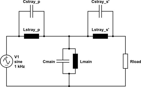
If you consider a standard 50/60Hz transformer, the main reactance is made huge by putting a lot of windings on an iron core. We cannot do that if we had a huge air gap. Our main inductance is not much higher than the stray inductances. So we have to increase the frequency. But this has a downfall, capacitances become important:

simulate this circuit
If we had to optimize this, it easy to see we cannot just increase the frequency. Because we also had to supply the reactive current through the main capacitance, and the size of our source is what we want to minimize. So the solution is to drive the transformer at the resonant frequency of its main inductance/capacitance.
(The main capacitance in other terms is also a stray capacitance, of course.)


