1
\$\begingroup\$

I've got an old circuit design I need to replicate, function wise, to fit into an existing larger design. Logic I can usually handle, anything with transistors starts to get me lost. My strength is in DFM and manufacturing, not necessarily electrical design. The original design functions as a simple on-off switch on a TTL logic circuit, with a separate IR LED source. Top circuit is the original design, bottom is my proposed alternate.

D1 is a photodarlington, Motorola MRD370, long obsolete and difficult to find at a decent price. Due to cost and availability I'd like to use a phototransistor instead of a photodarlington, but am concerned about enough gain. Hence the 2nd schematic with an additional 2N3904. Resistance value I haven't even tried to calculate yet. The original circuit is a TTL logic circuit, just can't figure out how to show that in the schematic. I have enough activity to post links now, so here's the original schematic I'm working from. Identical circuit is duplicated a few more times on the board, each for an independent photodarlington. http://www.siegecraft.us/images/IMGP5973.JPG
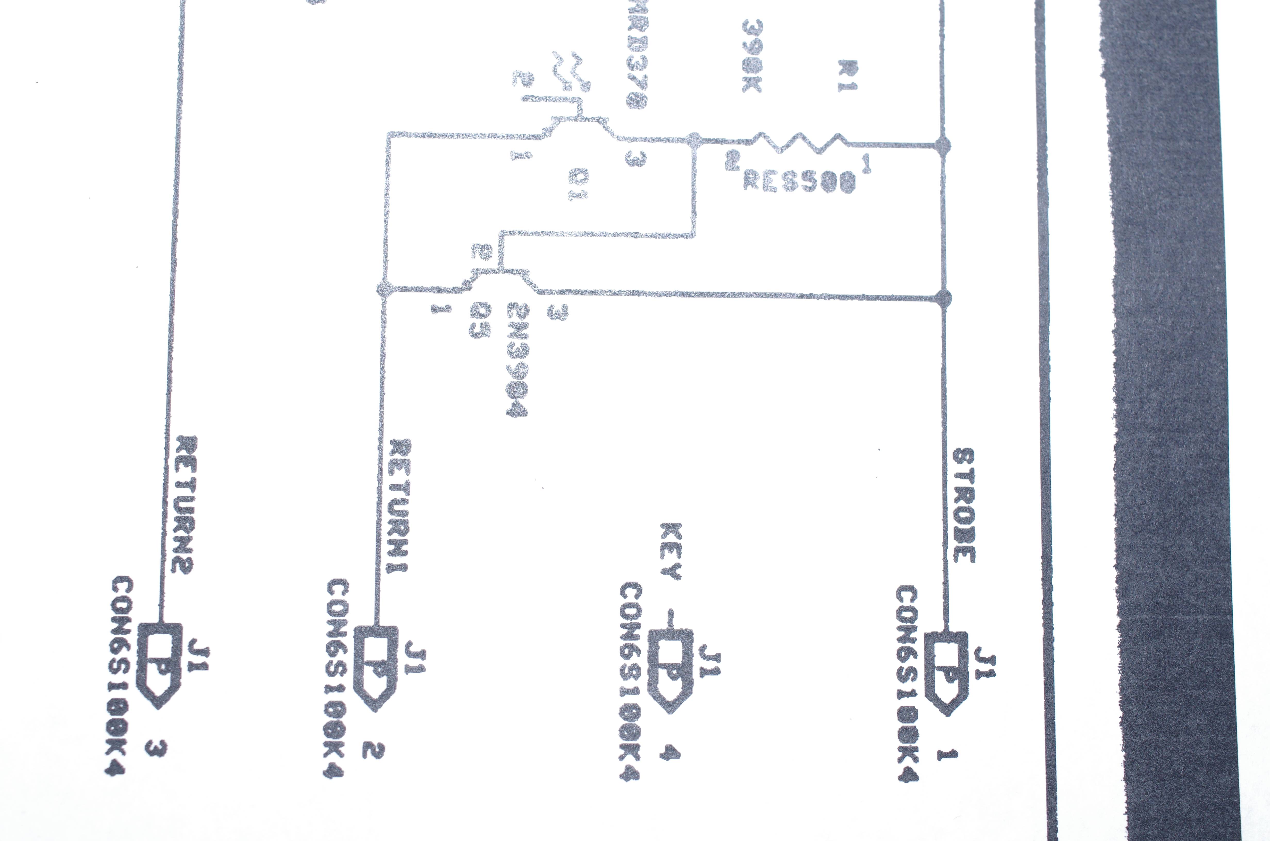
Would my proposed circuit be completely off the mark here? Photosensors are totally outside my practical experience. Switching time really isn't a big concern here, as the circuit is detecting the presence/absence of a stationary object. I added a 2nd proposed circuit, based on suggestions received. Left the first one to hopefully avoid confusion with changes.
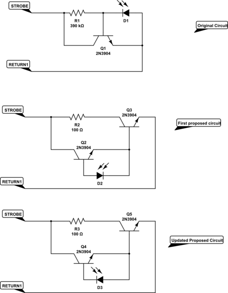
schematic

simulate this circuit – Schematic created using CircuitLab

\$\endgroup\$
13
  • 1
    \$\begingroup\$ Are you sure about that first one? It doesn't look right. \$\endgroup\$
    – Hearth
    Commented May 13, 2018 at 17:05
  • \$\begingroup\$ D1 and D2 are photodiodes. \$\endgroup\$ Commented May 13, 2018 at 17:09
  • \$\begingroup\$ In this schematic, yes, I used photodiodes. I didn't see an available option for phototransistors or photodarlingtons. The original circuit left the base leg unconnected. I'll double check that first circuit, the original schematic is pretty difficult to read, and I can't post photos yet. \$\endgroup\$
    – Hans
    Commented May 13, 2018 at 17:13
  • \$\begingroup\$ Verified the schematic on the first one again. I agree, it really does look odd to me as well, but I did confirm it via both an original schematic and also measurements on a PCB. That's part of my confusion, the original is just not what my research has turned up for a photodiode circuit of any kind. \$\endgroup\$
    – Hans
    Commented May 13, 2018 at 17:19
  • 1
    \$\begingroup\$ No, definitely not 9v, it's a TTL logic source. Again, limitation of the schematic software, never used it before. Hopefully this works to clarify. I'll edit the image link into the main post as well. siegecraft.us/images/IMGP5973.JPG \$\endgroup\$
    – Hans
    Commented May 13, 2018 at 17:32

1 Answer 1

1
\$\begingroup\$

I made some corrections according to the picture you posted.

There is nothing special about this phototransistor in the way is used here.

The higher current parameter ( up to 20 mA) is not used here since the bias resistor has a high value.

Simply use a normal phototransistor like BPW76 instead with the original schematic. It is pin to pin compatible.

\$\endgroup\$
1
  • \$\begingroup\$ That's even better. Means I can just use the existing boards to test as well. This way I'm only dealing with a single variable. Much appreciated. \$\endgroup\$
    – Hans
    Commented May 15, 2018 at 0:50

Your Answer

By clicking “Post Your Answer”, you agree to our terms of service and acknowledge you have read our privacy policy.

Not the answer you're looking for? Browse other questions tagged or ask your own question.