I'm modding an already built circuit which can operate from the current of a USB port about 90% of the time but in some specific cases it needs to draw more than the 500 mA the USB provides (it is also smart enough to shutdown itself if there's not enough current available).
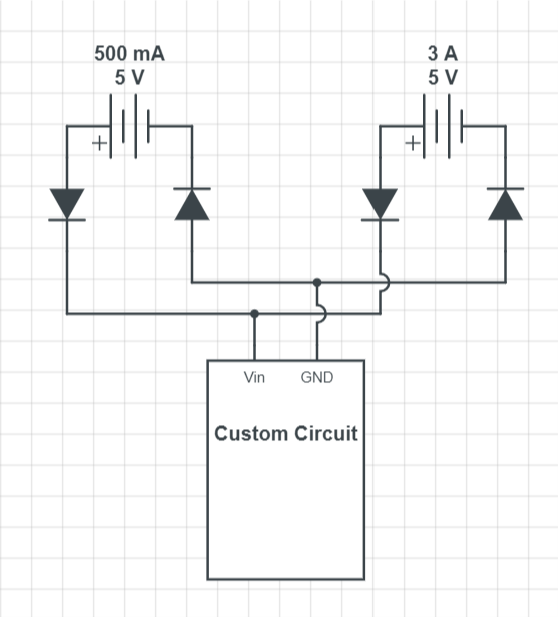
I want to add an external Power Supply to it, on that case, 5V @ 3 A. Both power sources will eventually end being connected in parallel at the same pins (the idea is having the custom circuit powered from either one of the power sources or even from both at the same time). Given the constraints (also for safety reasons), power from the external PSU must not leak on the USB plug nor vice versa (but very low voltage -- in the mV scale -- are acceptable). I used diodes and ended with something like this:
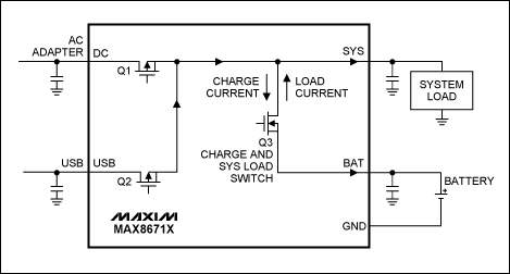
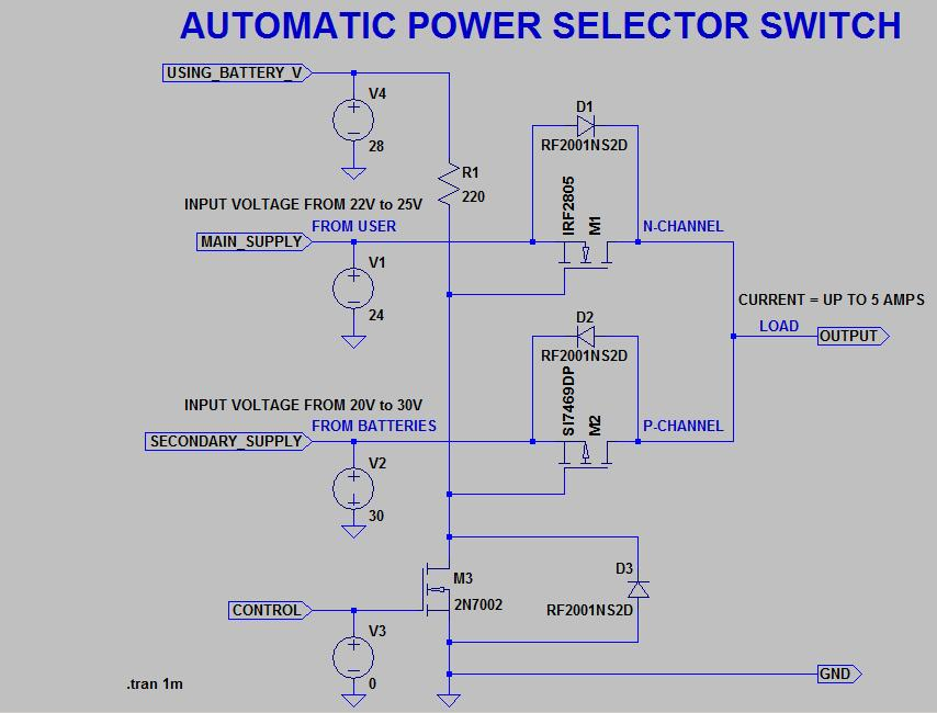
While it works good enough for what I'm trying to achieve, the drop-out voltage from the diodes are causing some stability issues in the custom circuit (even when using low drop-out Schottky diodes), and in this particular scenario I can't increase the voltage from either power sources, so, with some research I discovered the possibility of using a MOSFET to achieve the same but with a very small drop-out voltage when compared with the conventional diodes approach.
The linked article explains how to do that on the Vin line with a p-MOSFET, however I couldn't achieve the same in the GND line. I tried using n-MOSFET on those lines, and while it somewhat worked, I were still getting leakages in the power sources. So, how it's done? Are there any better approach to this?


