2
\$\begingroup\$

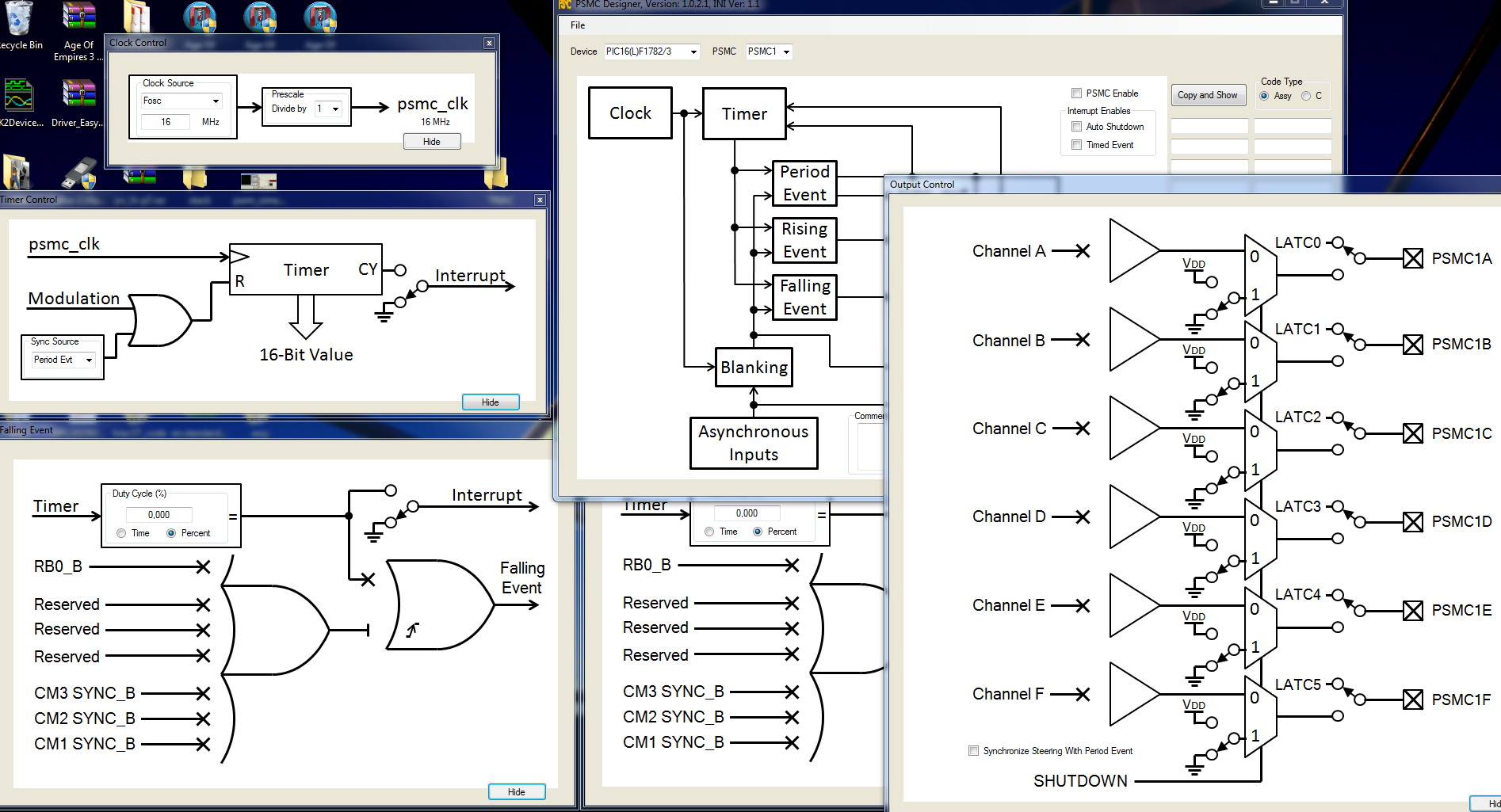
I'm trying to make PSMC1 in a 16F1782 work as a simple PWM generator. I've been banging my head against the wall for the past few days and figured that I had best ask for help.

I am using both MPLAB 8.92 and MPLAB-X 4.05 with a PICkit3 and either the target processor directly or using a AC244064 Emulation Debug Header attached to the target board.

The problem is that the timer in the module doesn't seem to be continuing to count. I have tried a variety of things to try and nail this down: I can pause the debug session, pre-load either / both the high or low byte of the timer registers with some arbitrary value, then restart the debug session. The timer always shows up as 0x0001 when the debug session is halted again and bit _PSMC1LD always goes LO.

I've tried both clocking from Fosc and the internal 64 MHz clock. Fosc is 4 MHz for this project. Although my board is laid out to use output PSMC1E, I've also tried it with the pin shown in the example code: PSMC1A.

I'm obviously doing something wrong and I'm hoping that some kind soul can point out my error.

The following contains two sections: first are the defines and initial register values that I write into the various PSMC registers during initialization, the second section is the disassembly output as shown in MPLAB-X v4.05. Note that in the disassembly listing, each instruction is shown twice: first: then shown as written in my code, then the disassembled code

;PSMC CONTROL REGISTER
    #define _P1MODE0    PSMC1CON,0  ;0000= 1 PWM  0001= same /w Comp o/p
    #define _P1MODE1    PSMC1CON,1  ;0010= PushPull  0011= same /w Comp o/p
    #define _P1MODE2    PSMC1CON,2  ;0100= P-P /w 4 o/p  0101= same /w Comp o/p
    #define _P1MODE3    PSMC1CON,3  ;0110= PulseSkip PWM  0111= same /w Comp o/p
                                    ;1000= ECCP Full Br Rev  1001 same /w For
                                    ;1010= Fix DC, Var Freq  1011 same /w Comp o/p
                                    ;1100= 3ph PWM   1101, 1110, 1111 reserved
    #define _P1DBRE     PSMC1CON,4  ;Rise Edge Dead Band Enable 1= Enabled
    #define _P1DBFE     PSMC1CON,5  ;Fall Edge Dead Band Enable 1= Enabled
    #define _PSMC1LD    PSMC1CON,6  ;0= Buffer Update done  1= Ready to Update
    #define _PSMC1EN    PSMC1CON,7  ;Enable: 1= Enabled
PSMC1CON_INIT   EQU b'11000000' ;enabled, 1 PWM, load steering & timing regs


;PSMC OUTPUT ENABLE CONTROL
    #define _P1OEA      PSMC1OEN,0  ;o/p Enable A  RC0
    #define _P1OEB      PSMC1OEN,1  ;           B  RC1
    #define _P1OEC      PSMC1OEN,2  ;           C  RC2
    #define _P1OED      PSMC1OEN,3  ;           D  RC3
    #define _P1OEE      PSMC1OEN,4  ;           E  RC4
    #define _P1OEF      PSMC1OEN,5  ;           F  RC5
PSMC1OEN_INIT   EQU b'00010000' ;pin RC4


;PSMC STEERING CONTROL  Zero in any bit position (A-F) disables that bit
    #define _P1STRA     PSMC1STR0,0 ;P1MODE= 000x (1ph) o/p
                                    ;P1MODE= 1100 (3ph) A,D HI  B,C,E,F LO 
    #define _P1STRB     PSMC1STR0,1 ;P1MODE= 0000 (1ph) 
                                    ;P1MODE= 0001 (1ph) comp o/p
                                    ;P1MODE= 1100 (3ph) A,F HI  C,C,D,E LO
    #define _P1STRC     PSMC1STR0,2 ;P1MODE= 000x (1ph) o/p
                                    ;P1MODE= 1100 (3ph) C,F HI  A,B,D,E LO                                       
    #define _P1STRD     PSMC1STR0,3 ;P1MODE= 000O (1ph) o/p
                                    ;P1MODE= 0001 (1ph) comp o/p
                                    ;P1MODE= 1100 (3ph) B,C HI  A,D,E,F LO
    #define _P1STRE     PSMC1STR0,4 ;P1MODE= 000x (1ph) o/p
                                    ;P1MODE= 1100 (3ph) B,E HI  A,C,D,F LO
    #define _P1STRF     PSMC1STR0,5 ;P1MODE= 0000 (1ph) o/p
                                    ;P1MODE= 0001 (1ph) comp o/p
                                    ;P1MODE= 1100 (3ph) D,E HI  A,B,C,F LO
                                    ;Note: lowest bit takes precedence for 3ph
PSMC1STR0_INIT  EQU b'00010000' ;pin rc4


;PSMC POLARITY CONTROL
    #define _P1POLA     PSMC1POL,0  ;o/p A Polarity  0= Act HI  1= Act LO
    #define _P1POLB     PSMC1POL,1  ;    B
    #define _P1POLC     PSMC1POL,2  ;    C
    #define _P1POLD     PSMC1POL,3  ;    D
    #define _P1POLE     PSMC1POL,4  ;    E
    #define _P1POLF     PSMC1POL,5  ;    F
    #define _P1INPOL    PSMC1POL,6  ;PSMC1 i/p Polarity  0= Act HI  1= Act LO
PSMC1POL_INIT   EQU b'00000000' ;active HI


;PSMC MODULATION CONTROL
    #define _P1MSRC0    PSMC1MDL,0  ;Modulation Source: 0000= P1MDLBIT
    #define _P1MSRC1    PSMC1MDL,1  ;0001= C1OUT  0010= C2OUT  0011= C3OUT
    #define _P1MSRC2    PSMC1MDL,2  ;1000 reserved  0101= CCP1  0110= CCP2  
    #define _P1MSRC3    PSMC1MDL,3  ;0111 reserved  1000= PSMC1IN pin
    #define _P1MDLBIT   PSMC1MDL,5  ;
    #define _P1MDLPOL   PSMC1MDL,6  ;Mod Select Polarity  0= Mod=1  1= Mod=0
    #define _P1MDLEN    PSMC1MDL,7  ;Mod enable: 0= No Modulation
                                    ;1= active when Mod signal
PSMC1MDL_INIT   EQU b'00000000' ;no modulation


;PSMC1 SYNCHRONIZATION CONTROL
    #define _P1SYNC0    PSMC1SYNC,0 ;00= Sync /w Period Event  01= reserved
    #define _P1SYNC1    PSMC1SYNC,1 ;10= Sync /w PSMC2 module  11= reserved
PSMC1SYNC_INIT  EQU b'00000000' ;sync /w period event


;PSMC CLOCK CONTROL
    #define _P1CSRC0    PSMC1CLK,0  ;00= Fosc  01= 64MHz  
    #define _P1CSRC1    PSMC1CLK,1  ;10= PSMC1clk pin  11= reserved
    #define _P1CPRE0    PSMC1CLK,4  ;00= Clk /1  01= Clk /2
    #define _P1CPRE1    PSMC1CLK,5  ;10= Clk /4  11= Clk /8
PSMC1CLK_INIT   EQU b'00000000' ;Fosc /1


;PSMC BLANKING CONTROL
    #define _P1REBM0    PSMC1BLNK,0 ;Rise Edge Blanking  00= None  01= Immediate
    #define _P1REBM1    PSMC1BLNK,1 ;                 10= reserved  11= reserved
    #define _P1FEBM0    PSMC1BLNK,4 ;Fall Edge Blanking  00= None  01= Immediate
    #define _P1FEBM1    PSMC1BLNK,5 ;                 10= reserved  11= reserved
PSMC1BLNK_INIT  EQU b'00000000' ;no blanking


;PSMC RISING EDGE BLANKED SOURCE  0= not source of blanking  1= source blanks
    #define _P1REBSC1   PSMC1REBS,1 ;Blanked from sync_C1OUT
    #define _P1REBSC2   PSMC1REBS,2 ;Blanked from sync_C2OUT
    #define _P1REBSC3   PSMC1REBS,3 ;Blanked from sync_C3OUT
    #define _P1REBSIN   PSMC1REBS,7 ;Blanked from PSMC1IN pin
PSMC1REBS_INIT  EQU b'00000000' ;no blanking


;PSMC FALLING EDGE BLANKED SOURCE  0= not source of blanking  1= source blanks
    #define _P1FEBSC1   PSMC1FEBS,1 ;Blanked from sync_C1OUT
    #define _P1FEBSC2   PSMC1FEBS,2 ;Blanked from sync_C2OUT
    #define _P1FEBSC3   PSMC1FEBS,3 ;Blanked from sync_C3OUT
    #define _P1FEBSIN   PSMC1FEBS,7 ;Blanked from PSMC1IN pin 
PSMC1FEBS_INIT  EQU b'00000000' ;no blanking


;PSMC PHASE SOURCE (Rise Edge Event) 0 means that signal does NOT cause event
    #define _P1PHST     PSMC1PHS,0  ;1= Rise Edge Event when PSMCxTMR = PSMCxPH
    #define _P1PHSC1    PSMC1PHS,1  ;1= Rise Edge Event when sync_C1OUT goes true
    #define _P1PHSC2    PSMC1PHS,2  ;1= Rise Edge Event when sync_C2OUT goes true
    #define _P1PHSC3    PSMC1PHS,3  ;1= Rise Edge Event when sync_C3OUT goes true
    #define _P1PHSIN    PSMC1PHS,7  ;1= Rise Edge Event when PSMC1IN pin goes true
PSMC1PHS_INIT   EQU b'00000001' ;from timebase


;PSMC DUTY CYCLE SOURCE (Fall Edge Event) 0 means that signal does NOT cause event
    #define _P1DCST     PSMC1DCS,0  ;1= Fall Edge Event when PSMCxTMR = PSMCxDC
    #define _P1DCSC1    PSMC1DCS,1  ;1= Fall Edge Event when sync_C1OUT goes true
    #define _P1DCSC2    PSMC1DCS,2  ;1= Fall Edge Event when sync_C2OUT goes true
    #define _P1DCSC3    PSMC1DCS,3  ;1= Fall Edge Event when sync_C3OUT goes true
    #define _P1DCSIN    PSMC1DCS,7  ;1= Fall Edge Event when PSMC1IN pin goes true
PSMC1DCS_INIT   EQU b'00000001' ;from timebase


;PSMC PERIOD SOURCE                 0 means that signal does NOT cause event
    #define _P1PRST     PSMC1PRS,0  ;1= Period Event when PSMCxTMR = PSMCxPR
    #define _P1PRSC1    PSMC1PRS,1  ;1= Period Event when sync_C1OUT goes true
    #define _P1PRSC2    PSMC1PRS,2  ;1= Period Event when sync_C2OUT goes true
    #define _P1PRSC3    PSMC1PRS,3  ;1= Period Event when sync_C3OUT goes true
    #define _P1PRSIN    PSMC1PRS,7  ;1= Period Event when PSMC1IN pin goes true
PSMC1PRS_INIT   EQU b'00000001' ;from timebase


;PSMC AUTO-SHUTDOWN CONTROL ("AS")
    #define _P1ASDOV    PSMC1ASDC,0 ;AS OverRide: 0= No Effect  1= 
    #define _P1ARSEN    PSMC1ASDC,5 ;AS Auto-Restart 1= auto  0= require restart
    #define _P1ASDEN    PSMC1ASDC,6 ;AS Enable: 0= No AS  1= Enabled
    #define _P1ASE      PSMC1ASDC,7 ;AS Status: 0= normal  1= Shutdown occurred
PSMC1ASDC_INIT  EQU b'00000000' ;no auto shutdown


;PSMC AUTO-SHUTDOWN OUTPUT LEVEL  Sets Pin Level when AutoShutdown occurs
    #define _P1ASDLA    PSMC1ASDD,0 ;Pin A  0= pin goes LO  1= pin goes HI
    #define _P1ASDLB    PSMC1ASDD,1 ;    B
    #define _P1ASDLC    PSMC1ASDD,2 ;    C
    #define _P1ASDLD    PSMC1ASDD,3 ;    D
    #define _P1ASDLE    PSMC1ASDD,4 ;    E
    #define _P1ASDLF    PSMC1ASDD,5 ;    F
PSMC1ASDD_INIT  EQU b'00000000' ;non-active (shutdown) levels all LO (0)


;PSMC AUTO-SHUTDOWN SOURCE  0= signal does NOT cause shutdown  1= signal enabled
    #define _P1ASDSC1   PSMC1ASDS,1 ;AS occurs when sync_C1OUT output goes true
    #define _P1ASDSC2   PSMC1ASDS,2 ;AS occurs when sync_C2OUT output goes true
    #define _P1ASDSC3   PSMC1ASDS,3 ;AS occurs when sync_C3OUT output goes true
    #define _P1ASDSIN   PSMC1ASDS,7 ;AS occurs when PSMC1IN pin goes true
PSMC1ASDS_INIT  EQU b'00000000' ;no auto shutdown


;PSMC TIMEBASE INTERRUPT CONTROL
    #define _P1TPRIF    PSMC1INT,0  ;1= 16-bit PSMC1TMR matched PSMC1PR<15:0>
    #define _P1TDCIF    PSMC1INT,1  ;1= 16-bit PSMC1TMR matched PSMC1DC<15:0>
    #define _P1TPHIF    PSMC1INT,2  ;1= 16-bit PSMC1TMR matched PSMCxPH<15:0>
    #define _P1TOVIF    PSMC1INT,3  ;1= 16-bit PSMC1TMR overflowed 0xFFFF -> 0x0 
    #define _P1TPRIE    PSMC1INT,4  ;1= TimeBase Period match ints enabled
    #define _P1TDCIE    PSMC1INT,5  ;1= TimeBase Duty Cycle match ints enabled
    #define _P1TPHIE    PSMC1INT,6  ;1= TimeBase Phase Match ints enabled
    #define _P1TOVIE    PSMC1INT,7  ;1= TimeBase overflow ints enabled
PSMC1INT_INIT   EQU b'00000000' ;no interrupts


!; Single-phase PWM PSMC setup
!; Fully synchronous operation
!; Period =
!; Duty cycle = 50%

!    SETBSR      PSMC1CON
0x1DE: MOVLB 0x10
!    movlw       0x02            ; set period
0x1DF: MOVLW 0x2
!    movwf       RBS(PSMC1PRH)
0x1E0: MOVWF PSMC1PRH
!    movlw       0x7F
0x1E1: MOVLW 0x7F
!    movwf       RBS(PSMC1PRL)
0x1E2: MOVWF PSMC1PR

!    movlw       0x01            ; set duty cycle
0x1E3: MOVLW 0x1
!    movwf       RBS(PSMC1DCH)
0x1E4: MOVWF PSMC1DCH
!    movlw       0x3F
0x1E5: MOVLW 0x3F
!    movwf       RBS(PSMC1DCL)
0x1E6: MOVWF PSMC1DC

!    clrf        RBS(PSMC1PHH)   ; no phase offset
0x1E7: CLRF PSMC1PHH
!    clrf        RBS(PSMC1PHL)
0x1E8: CLRF PSMC1PH
!    movlw       PSMC1CLK_INIT
0x1E9: MOVLW 0x0
!    movwf       RBS(PSMC1CLK)
0x1EA: MOVWF PSMC1CLK

!; output on E, normal polarity
!    bcf         BBS(_P1STRA)    ;chip pwr-up default is HI
0x1EB: BCF PSMC1STR0, 0x0
!    bsf         BBS(_P1STRE)
0x1EC: BSF PSMC1STR0, 0x4
!    bcf         BBS(_P1POLE)
0x1ED: BCF PSMC1POL, 0x4
!    bsf         BBS(_P1OEE)
0x1EE: BSF PSMC1OEN, 0x4

!; set time base as source for all events
!    bsf         BBS(_P1PRST)
0x1EF: BSF PSMC1PRS, 0x0
!    bsf         BBS(_P1PHST)
0x1F0: BSF PSMC1PHS, 0x0
!    bsf         BBS(_P1DCST)
0x1F1: BSF PSMC1DCS, 0x0

!; enable PSMC in Single-Phase Mode
!; this also loads steering and time buffers
!    movlw       PSMC1CON_INIT
0x1F2: MOVLW 0xC0
!    movwf       RBS(PSMC1CON)
0x1F3: MOVWF PSMC1CON

!    SETBSR      TRISC
0x1F4: MOVLB 0x1
!    bcf         BBS(TRISC,4)    ; enable pin driver
0x1F5: BCF TRISC, 0x4
!    
!    rampg0
0x1F6: MOVLB 0x0
\$\endgroup\$
2
  • 1
    \$\begingroup\$ Hi Dwayne. Unfortunately I am not an assembly language guy, using C and only writing small pieces in assembly. Regardless, I have discovered that the Microchip in-circuit debugger feature does not always behave well for timer functions. You might try running using "release" code (no debugger) and test it by flipping an unused pin to check your timing. I think there's a good chance that your code is just fine. \$\endgroup\$ Commented May 18, 2018 at 21:50
  • 1
    \$\begingroup\$ Great suggestion. I had tried this early on and just did it again - no joy. Still struggling. \$\endgroup\$ Commented May 20, 2018 at 3:26

3 Answers 3

1
+150
\$\begingroup\$

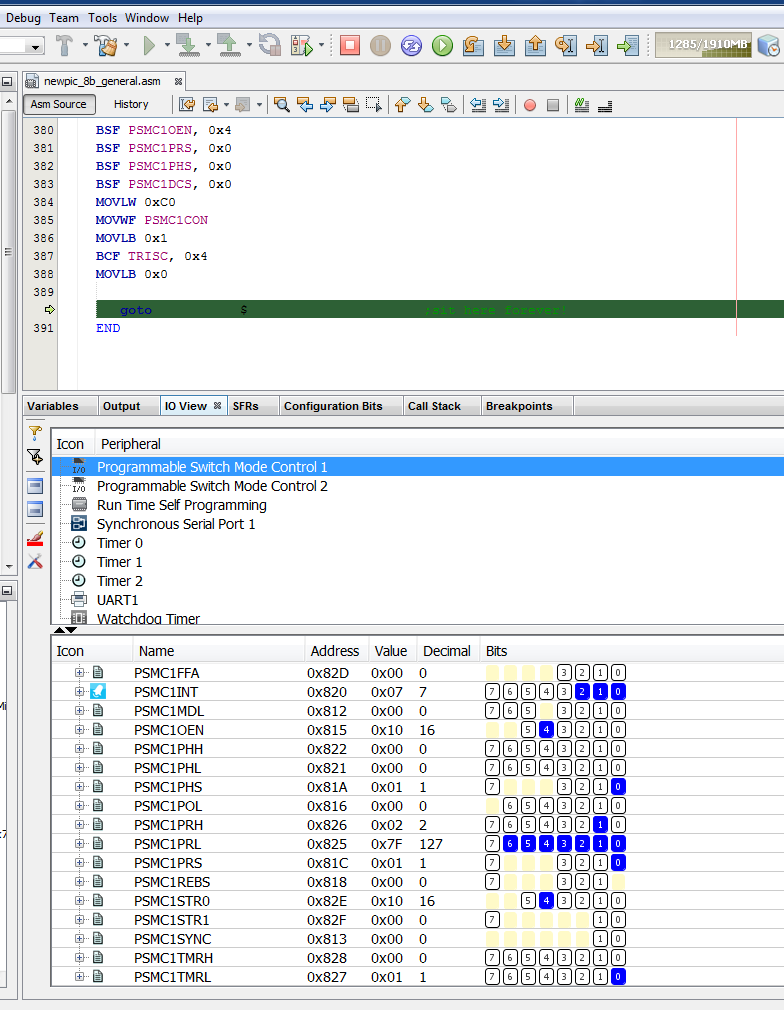
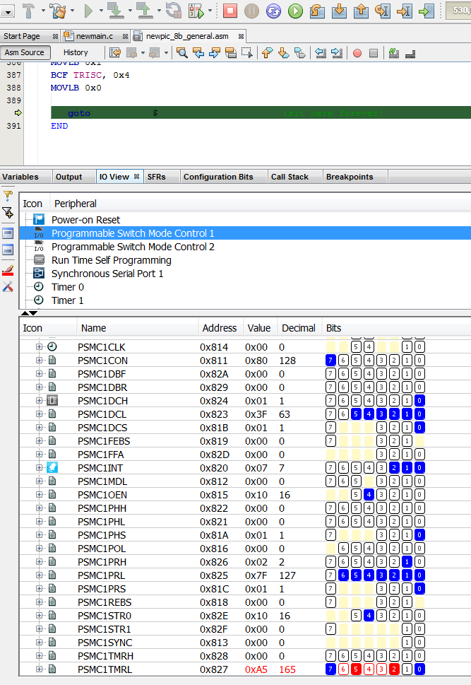
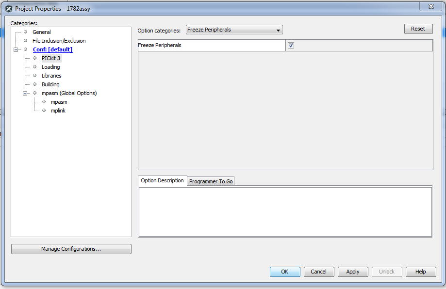
Tested code, works as it should both on simulator and real pic. Problem seems related to Freeze Peripherals. UPDATE: confirmed behaviour on real board, debug with pickit 3 without header. Unmark Freeze Peripheral checkbox

freeze peripherals ON  **freeze peripherals ON, default** freeze peripherals OFF  **freeze peripherals OFF** enter image description here enter image description here

    ;*******************************************************************************
    ; Reset Vector
    ;*******************************************************************************

    RES_VECT  CODE    0x0000            ; processor reset vector
        GOTO    START                   ; go to beginning of program

    ; MAIN PROGRAM
    ;*******************************************************************************
    #include "p16f1782.inc"

     #define NOBANKWARN & 0x7F

    ; CONFIG1
    ; __config 0x37E4
     __CONFIG _CONFIG1, _FOSC_INTOSC & _WDTE_OFF & _PWRTE_OFF & _MCLRE_ON & _CP_OFF & _CPD_OFF & _BOREN_ON & _CLKOUTEN_OFF & _IESO_ON & _FCMEN_ON
    ; CONFIG2
    ; __config 0x3FFF
     __CONFIG _CONFIG2, _WRT_OFF & _VCAPEN_OFF & _PLLEN_ON & _STVREN_ON & _BORV_LO & _LPBOR_OFF & _LVP_ON

    MAIN_PROG CODE                      ; let linker place main program

     START
 ;old setup
    ;PSMC CONTROL REGISTER
        #define _P1MODE0    PSMC1CON,0  ;0000= 1 PWM  0001= same /w Comp o/p
        #define _P1MODE1    PSMC1CON,1  ;0010= PushPull  0011= same /w Comp o/p
        #define _P1MODE2    PSMC1CON,2  ;0100= P-P /w 4 o/p  0101= same /w Comp o/p
        #define _P1MODE3    PSMC1CON,3  ;0110= PulseSkip PWM  0111= same /w Comp o/p
                                        ;1000= ECCP Full Br Rev  1001 same /w For
                                        ;1010= Fix DC, Var Freq  1011 same /w Comp o/p
                                        ;1100= 3ph PWM   1101, 1110, 1111 reserved
        #define _P1DBRE     PSMC1CON,4  ;Rise Edge Dead Band Enable 1= Enabled
        #define _P1DBFE     PSMC1CON,5  ;Fall Edge Dead Band Enable 1= Enabled
        #define _PSMC1LD    PSMC1CON,6  ;0= Buffer Update done  1= Ready to Update
        #define _PSMC1EN    PSMC1CON,7  ;Enable: 1= Enabled
    PSMC1CON_INIT   EQU b'11000000' ;enabled, 1 PWM, load steering & timing regs


    ;PSMC OUTPUT ENABLE CONTROL
        #define _P1OEA      PSMC1OEN,0  ;o/p Enable A  RC0
        #define _P1OEB      PSMC1OEN,1  ;           B  RC1
        #define _P1OEC      PSMC1OEN,2  ;           C  RC2
        #define _P1OED      PSMC1OEN,3  ;           D  RC3
        #define _P1OEE      PSMC1OEN,4  ;           E  RC4
        #define _P1OEF      PSMC1OEN,5  ;           F  RC5
    PSMC1OEN_INIT   EQU b'00010000' ;pin RC4


    ;PSMC STEERING CONTROL  Zero in any bit position (A-F) disables that bit
        #define _P1STRA     PSMC1STR0,0 ;P1MODE= 000x (1ph) o/p
                                        ;P1MODE= 1100 (3ph) A,D HI  B,C,E,F LO 
        #define _P1STRB     PSMC1STR0,1 ;P1MODE= 0000 (1ph) 
                                        ;P1MODE= 0001 (1ph) comp o/p
                                        ;P1MODE= 1100 (3ph) A,F HI  C,C,D,E LO
        #define _P1STRC     PSMC1STR0,2 ;P1MODE= 000x (1ph) o/p
                                        ;P1MODE= 1100 (3ph) C,F HI  A,B,D,E LO                                       
        #define _P1STRD     PSMC1STR0,3 ;P1MODE= 000O (1ph) o/p
                                        ;P1MODE= 0001 (1ph) comp o/p
                                        ;P1MODE= 1100 (3ph) B,C HI  A,D,E,F LO
        #define _P1STRE     PSMC1STR0,4 ;P1MODE= 000x (1ph) o/p
                                        ;P1MODE= 1100 (3ph) B,E HI  A,C,D,F LO
        #define _P1STRF     PSMC1STR0,5 ;P1MODE= 0000 (1ph) o/p
                                        ;P1MODE= 0001 (1ph) comp o/p
                                        ;P1MODE= 1100 (3ph) D,E HI  A,B,C,F LO
                                        ;Note: lowest bit takes precedence for 3ph
    PSMC1STR0_INIT  EQU b'00010000' ;pin rc4


    ;PSMC POLARITY CONTROL
        #define _P1POLA     PSMC1POL,0  ;o/p A Polarity  0= Act HI  1= Act LO
        #define _P1POLB     PSMC1POL,1  ;    B
        #define _P1POLC     PSMC1POL,2  ;    C
        #define _P1POLD     PSMC1POL,3  ;    D
        #define _P1POLE     PSMC1POL,4  ;    E
        #define _P1POLF     PSMC1POL,5  ;    F
        #define _P1INPOL    PSMC1POL,6  ;PSMC1 i/p Polarity  0= Act HI  1= Act LO
    PSMC1POL_INIT   EQU b'00000000' ;active HI


    ;PSMC MODULATION CONTROL
        #define _P1MSRC0    PSMC1MDL,0  ;Modulation Source: 0000= P1MDLBIT
        #define _P1MSRC1    PSMC1MDL,1  ;0001= C1OUT  0010= C2OUT  0011= C3OUT
        #define _P1MSRC2    PSMC1MDL,2  ;1000 reserved  0101= CCP1  0110= CCP2  
        #define _P1MSRC3    PSMC1MDL,3  ;0111 reserved  1000= PSMC1IN pin
        #define _P1MDLBIT   PSMC1MDL,5  ;
        #define _P1MDLPOL   PSMC1MDL,6  ;Mod Select Polarity  0= Mod=1  1= Mod=0
        #define _P1MDLEN    PSMC1MDL,7  ;Mod enable: 0= No Modulation
                                        ;1= active when Mod signal
    PSMC1MDL_INIT   EQU b'00000000' ;no modulation


    ;PSMC1 SYNCHRONIZATION CONTROL
        #define _P1SYNC0    PSMC1SYNC,0 ;00= Sync /w Period Event  01= reserved
        #define _P1SYNC1    PSMC1SYNC,1 ;10= Sync /w PSMC2 module  11= reserved
    PSMC1SYNC_INIT  EQU b'00000000' ;sync /w period event


    ;PSMC CLOCK CONTROL
        #define _P1CSRC0    PSMC1CLK,0  ;00= Fosc  01= 64MHz  
        #define _P1CSRC1    PSMC1CLK,1  ;10= PSMC1clk pin  11= reserved
        #define _P1CPRE0    PSMC1CLK,4  ;00= Clk /1  01= Clk /2
        #define _P1CPRE1    PSMC1CLK,5  ;10= Clk /4  11= Clk /8
    PSMC1CLK_INIT   EQU b'00000000' ;Fosc /1


    ;PSMC BLANKING CONTROL
        #define _P1REBM0    PSMC1BLNK,0 ;Rise Edge Blanking  00= None  01= Immediate
        #define _P1REBM1    PSMC1BLNK,1 ;                 10= reserved  11= reserved
        #define _P1FEBM0    PSMC1BLNK,4 ;Fall Edge Blanking  00= None  01= Immediate
        #define _P1FEBM1    PSMC1BLNK,5 ;                 10= reserved  11= reserved
    PSMC1BLNK_INIT  EQU b'00000000' ;no blanking


    ;PSMC RISING EDGE BLANKED SOURCE  0= not source of blanking  1= source blanks
        #define _P1REBSC1   PSMC1REBS,1 ;Blanked from sync_C1OUT
        #define _P1REBSC2   PSMC1REBS,2 ;Blanked from sync_C2OUT
        #define _P1REBSC3   PSMC1REBS,3 ;Blanked from sync_C3OUT
        #define _P1REBSIN   PSMC1REBS,7 ;Blanked from PSMC1IN pin
    PSMC1REBS_INIT  EQU b'00000000' ;no blanking


    ;PSMC FALLING EDGE BLANKED SOURCE  0= not source of blanking  1= source blanks
        #define _P1FEBSC1   PSMC1FEBS,1 ;Blanked from sync_C1OUT
        #define _P1FEBSC2   PSMC1FEBS,2 ;Blanked from sync_C2OUT
        #define _P1FEBSC3   PSMC1FEBS,3 ;Blanked from sync_C3OUT
        #define _P1FEBSIN   PSMC1FEBS,7 ;Blanked from PSMC1IN pin 
    PSMC1FEBS_INIT  EQU b'00000000' ;no blanking


    ;PSMC PHASE SOURCE (Rise Edge Event) 0 means that signal does NOT cause event
        #define _P1PHST     PSMC1PHS,0  ;1= Rise Edge Event when PSMCxTMR = PSMCxPH
        #define _P1PHSC1    PSMC1PHS,1  ;1= Rise Edge Event when sync_C1OUT goes true
        #define _P1PHSC2    PSMC1PHS,2  ;1= Rise Edge Event when sync_C2OUT goes true
        #define _P1PHSC3    PSMC1PHS,3  ;1= Rise Edge Event when sync_C3OUT goes true
        #define _P1PHSIN    PSMC1PHS,7  ;1= Rise Edge Event when PSMC1IN pin goes true
    PSMC1PHS_INIT   EQU b'00000001' ;from timebase


    ;PSMC DUTY CYCLE SOURCE (Fall Edge Event) 0 means that signal does NOT cause event
        #define _P1DCST     PSMC1DCS,0  ;1= Fall Edge Event when PSMCxTMR = PSMCxDC
        #define _P1DCSC1    PSMC1DCS,1  ;1= Fall Edge Event when sync_C1OUT goes true
        #define _P1DCSC2    PSMC1DCS,2  ;1= Fall Edge Event when sync_C2OUT goes true
        #define _P1DCSC3    PSMC1DCS,3  ;1= Fall Edge Event when sync_C3OUT goes true
        #define _P1DCSIN    PSMC1DCS,7  ;1= Fall Edge Event when PSMC1IN pin goes true
    PSMC1DCS_INIT   EQU b'00000001' ;from timebase


    ;PSMC PERIOD SOURCE                 0 means that signal does NOT cause event
        #define _P1PRST     PSMC1PRS,0  ;1= Period Event when PSMCxTMR = PSMCxPR
        #define _P1PRSC1    PSMC1PRS,1  ;1= Period Event when sync_C1OUT goes true
        #define _P1PRSC2    PSMC1PRS,2  ;1= Period Event when sync_C2OUT goes true
        #define _P1PRSC3    PSMC1PRS,3  ;1= Period Event when sync_C3OUT goes true
        #define _P1PRSIN    PSMC1PRS,7  ;1= Period Event when PSMC1IN pin goes true
    PSMC1PRS_INIT   EQU b'00000001' ;from timebase


    ;PSMC AUTO-SHUTDOWN CONTROL ("AS")
        #define _P1ASDOV    PSMC1ASDC,0 ;AS OverRide: 0= No Effect  1= 
        #define _P1ARSEN    PSMC1ASDC,5 ;AS Auto-Restart 1= auto  0= require restart
        #define _P1ASDEN    PSMC1ASDC,6 ;AS Enable: 0= No AS  1= Enabled
        #define _P1ASE      PSMC1ASDC,7 ;AS Status: 0= normal  1= Shutdown occurred
    PSMC1ASDC_INIT  EQU b'00000000' ;no auto shutdown


    ;PSMC AUTO-SHUTDOWN OUTPUT LEVEL  Sets Pin Level when AutoShutdown occurs
        #define _P1ASDLA    PSMC1ASDD,0 ;Pin A  0= pin goes LO  1= pin goes HI
        #define _P1ASDLB    PSMC1ASDD,1 ;    B
        #define _P1ASDLC    PSMC1ASDD,2 ;    C
        #define _P1ASDLD    PSMC1ASDD,3 ;    D
        #define _P1ASDLE    PSMC1ASDD,4 ;    E
        #define _P1ASDLF    PSMC1ASDD,5 ;    F
    PSMC1ASDD_INIT  EQU b'00000000' ;non-active (shutdown) levels all LO (0)


    ;PSMC AUTO-SHUTDOWN SOURCE  0= signal does NOT cause shutdown  1= signal enabled
        #define _P1ASDSC1   PSMC1ASDS,1 ;AS occurs when sync_C1OUT output goes true
        #define _P1ASDSC2   PSMC1ASDS,2 ;AS occurs when sync_C2OUT output goes true
        #define _P1ASDSC3   PSMC1ASDS,3 ;AS occurs when sync_C3OUT output goes true
        #define _P1ASDSIN   PSMC1ASDS,7 ;AS occurs when PSMC1IN pin goes true
    PSMC1ASDS_INIT  EQU b'00000000' ;no auto shutdown


    ;PSMC TIMEBASE INTERRUPT CONTROL
        #define _P1TPRIF    PSMC1INT,0  ;1= 16-bit PSMC1TMR matched PSMC1PR<15:0>
        #define _P1TDCIF    PSMC1INT,1  ;1= 16-bit PSMC1TMR matched PSMC1DC<15:0>
        #define _P1TPHIF    PSMC1INT,2  ;1= 16-bit PSMC1TMR matched PSMCxPH<15:0>
        #define _P1TOVIF    PSMC1INT,3  ;1= 16-bit PSMC1TMR overflowed 0xFFFF -> 0x0 
        #define _P1TPRIE    PSMC1INT,4  ;1= TimeBase Period match ints enabled
        #define _P1TDCIE    PSMC1INT,5  ;1= TimeBase Duty Cycle match ints enabled
        #define _P1TPHIE    PSMC1INT,6  ;1= TimeBase Phase Match ints enabled
        #define _P1TOVIE    PSMC1INT,7  ;1= TimeBase overflow ints enabled
    PSMC1INT_INIT   EQU b'00000000' ;no interrupts


    ; new setup
        banksel OSCCON
     movlw B'11110010' ;//32MHz
     movwf OSCCON   NOBANKWARN

        BANKSEL PSMC1CON
        movlw   H'00'
        movwf   PSMC1CON
        movlw   H'00'
        movwf   PSMC1MDL
        movlw   H'00'
        movwf   PSMC1SYNC
        movlw   H'01'
        movwf   PSMC1CLK
        movlw   H'00'
        movwf   PSMC1POL
        movlw   H'00'
        movwf   PSMC1BLNK
        movlw   H'00'
        movwf   PSMC1REBS
        movlw   H'00'
        movwf   PSMC1FEBS
        movlw   H'01'
        movwf   PSMC1PHS
        movlw   H'01'
        movwf   PSMC1DCS
        movlw   H'01'
        movwf   PSMC1PRS
        movlw   H'00'
        movwf   PSMC1ASDC
        movlw   H'10'
        movwf   PSMC1ASDL
        movlw   H'00'
        movwf   PSMC1ASDS
        movlw   H'00'
        movwf   PSMC1PHH
        movlw   H'00'
        movwf   PSMC1PHL
        movlw   H'02'
        movwf   PSMC1DCH
        movlw   H'80'
        movwf   PSMC1DCL
        movlw   H'04'
        movwf   PSMC1PRH
        movlw   H'FF'
        movwf   PSMC1PRL
        movlw   H'00'
        movwf   PSMC1DBR
        movlw   H'00'
        movwf   PSMC1DBF
        movlw   H'00'
        movwf   PSMC1FFA
        movlw   H'00'
        movwf   PSMC1BLKR
        movlw   H'00'
        movwf   PSMC1BLKF
        movlw   H'10'
        movwf   PSMC1STR0
        movlw   H'00'
        movwf   PSMC1STR1
        movlw   H'00'
        movwf   PSMC1INT
        movlw   H'10'
        movwf   PSMC1OEN
        movlw   H'80'
        movwf   PSMC1CON
        BANKSEL PIE4
        movlw   H'EE'
        andwf   PIE4,f
        movlw   H'00'
        iorwf   PIE4,f

    BCF TRISC, 0x4
    MOVLB 0x0

       goto           $                      ;sit here forever!
    END

enter image description here

\$\endgroup\$
5
  • \$\begingroup\$ Can you include a copy of the source code that you used? I'll copy / paste that into my board and verify functionality. Many thanks! \$\endgroup\$ Commented May 24, 2018 at 16:15
  • \$\begingroup\$ @DwayneReid, just update answer. my assy skills are basic, added some config in order to debug and used your code for the rest. \$\endgroup\$
    – johnger
    Commented May 24, 2018 at 16:17
  • \$\begingroup\$ I haven't yet had a chance to test what you wrote but I'm awarding the bounty anyway. Hope to be testing this later in the morning (Friday) but the bounty would expire before then. \$\endgroup\$ Commented May 25, 2018 at 5:38
  • 1
    \$\begingroup\$ I'll post another comment after I have tested your code - and update my question with what I find as well. Many thanks! \$\endgroup\$ Commented May 25, 2018 at 5:38
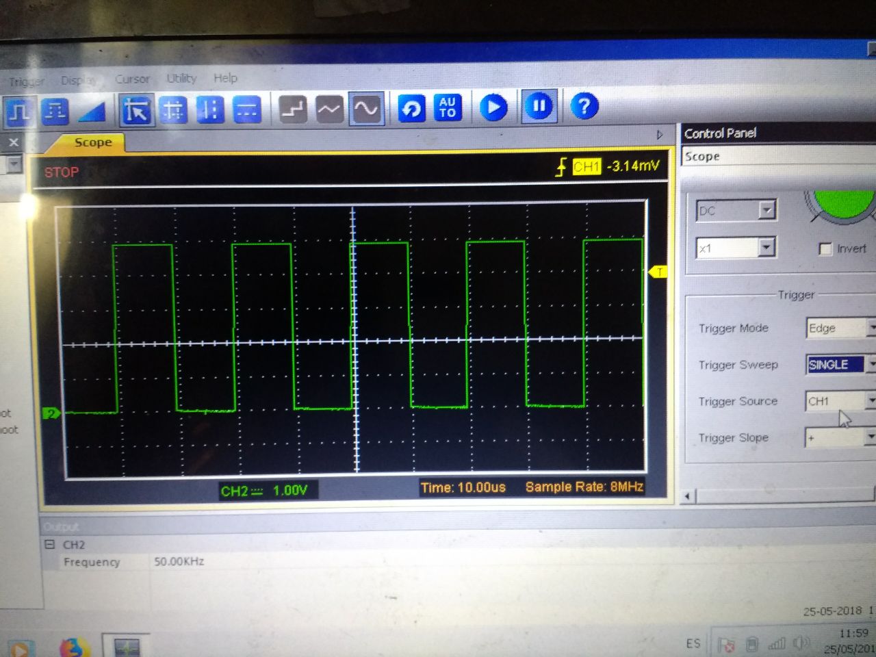
  • \$\begingroup\$ now Fosc is 32MHz, PSMC clock 64MHz, frequency 50KHz, duty 50%, output PSMC1E. \$\endgroup\$
    – johnger
    Commented May 25, 2018 at 10:13
2
\$\begingroup\$

Well, this has been a learning experience! Many thanks, johnger, for your detailed answer.

Several issues at play here. Main issue was complete unfamiliarity with this module. Second issue was a hardware problem on both of my prototype test boards.

I stripped johnger's code down to the bare minimum and ran it on my board. No output on pin RC4. Since this is known good code, I went looking for hardware problems. Created a tiny program that just toggles all of the Port C pins HI and LO - still no signal from pin RC4.

Found a bad solder joint right where the SOIC package pin (pin 15) went onto the trace. Solder joint looked perfect under the microscope, which is why it wasn't detected earlier.

Not sure yet what the problem was with the other board - this has 30 AWG wire-wrap wires soldered to the SOIC footprint where the PIC is supposed to go. The other ends of the wires go between a pair of stacked 28-pin machined-pin IC sockets which are plugged into the AC244064 Emulation Debug Header. Note: the IC socket connections on the debug header are mirrored, just like all of Microchip's previous debug or emulation headers.

Anyway, the PSMC module on that board is now working as well. Waiting for it to stop working at some point: Murphy says that "Problems that go away by themselves come back by themselves". . But now that I've seen it working, I can fix it if it stops.

johnger also nailed the problem why I couldn't see the PSMC module registers change whenever I halted the processor. Removing the check-mark from the "Freeze Peripherals" fixed that problem.

\$\endgroup\$
0
\$\begingroup\$

define _P1TOVIF PSMC1INT,3 ;1= 16-bit PSMC1TMR overflowed 0xFFFF -> 0x0

Where is your code to check for overflow, as in a bit test of '_P1TOVIF PSMC1INT,3'? As I see it you can start and stop your counter, but what code do you have to catch the counter overflow? Is it an ISR? Does not need to be.

I looked at your code closely and could not find a bit test condition check. Obviously this 16 bit counter does not do more than stay at zero. There is no hardware to auto-reload the counter that I could see.

Unless we are missing something you need to poll for the overflow flag or have that flag trigger an ISR to reload the counter.

\$\endgroup\$
3
  • \$\begingroup\$ My limited understanding is that this module runs autonomously once it has been started. The period match resets the counter and it is, I think, supposed to start counting up from 1 again. Certainly there is NO mention in the documentation of needing to restart the counter after each period match. Do note that the counter is NOT supposed to overflow; rather, it is reset when the period match occurs. \$\endgroup\$ Commented May 20, 2018 at 3:25
  • \$\begingroup\$ From page 193 of the 16F1782/83 datasheet (DS40001579E) "All period events cause the PSMCxTMR counter to reset on the counting clock edge immediately following the period event. The PSMCxTMR counter resumes counting from zero on the counting clock edge after the period event Reset". \$\endgroup\$ Commented May 20, 2018 at 3:34
  • \$\begingroup\$ It is supposed to be that way, but a crucial flag is not set or something to start the "Automatic" functions. My answer may not be close to being correct, but something is missing in the code. I seriously doubt the IC has any malfunctions. \$\endgroup\$
    – user105652
    Commented May 20, 2018 at 5:00

Your Answer

By clicking “Post Your Answer”, you agree to our terms of service and acknowledge you have read our privacy policy.

Not the answer you're looking for? Browse other questions tagged or ask your own question.