0
\$\begingroup\$

I would like to know what should happen when i connect low resistance to arduino output.

People say it will get damaged because it cannot supply the current. But I cannot understand this because the transistor can never exceed his max current.

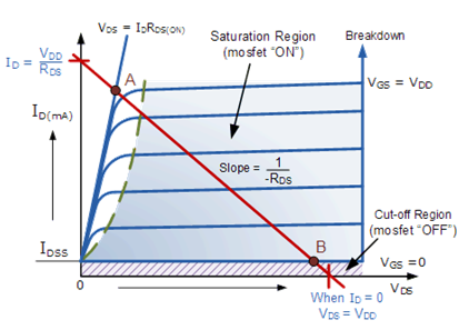
Lets say, we can to drive the output low. This is done by activating typical one mosfet inside arduino pin. Schematic overview is shown here under. Rd is in this example 100 ohm.

enter image description here

After activating the transtor, it will conduct. The current that will flow can be found by using loadline.

enter image description here

The lower the resistor, the highter the slope of loadline, the more current will flow. BUT, if the resistor is very low, also the voltage over the RD will discrease and the current will not increase anymore because the transistor is in saturation. This means that the transistor will never exceed the maximum current? So very low resistance can be used on I/O to draw max current. It will just give the max possible current.

So can I connect 100 ohm to arduino I/O or not?

I also wonder, IOL = 20mA, and VOL= 0,9 in TABLE. But when I check that graph VOL is about 0.3-0.5 when IOL is 20mA. This is for arduino. Please check answers below

\$\endgroup\$
2
  • \$\begingroup\$ A transistor in saturation can't go any more "on" only because it is fully on and will conduct as much as possible. \$\endgroup\$ Commented May 21, 2018 at 16:09
  • \$\begingroup\$ It's Ohm Law! . \$\endgroup\$
    – user76844
    Commented May 21, 2018 at 18:09

2 Answers 2

3
\$\begingroup\$

If you make the diagonal load line in your figure more vertical, it’ll intersect at higher \$I_S\$ and \$V_{DS}\$ values, so the power dissipated is going up.

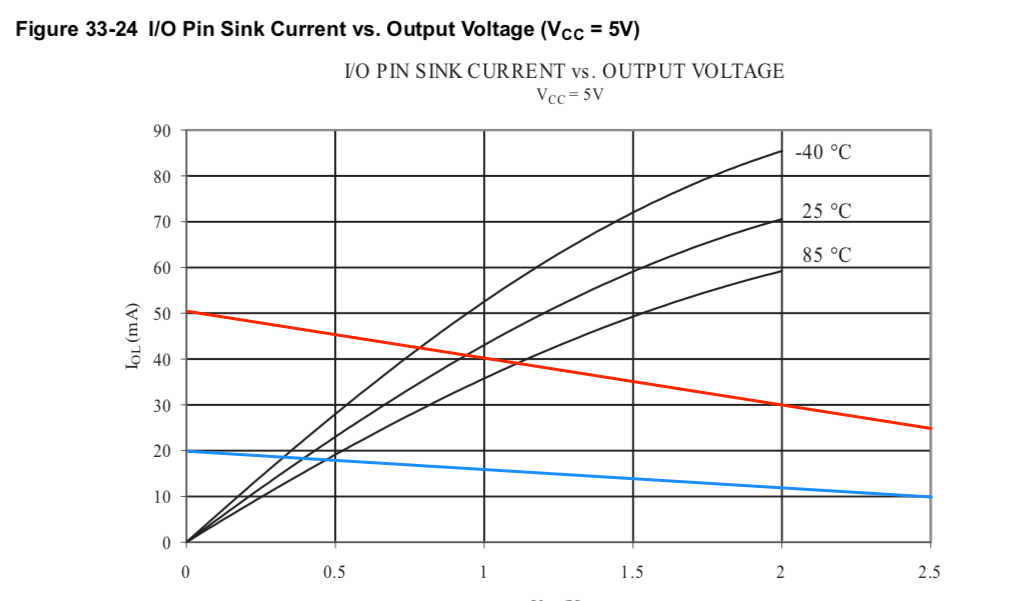
Start with a real output curve, such as this one from an AVR128A (see page 444 of the specification):

enter image description here

I added the red line to correspond to 100 ohms from 5V, and the blue one for 250 ohms from 5V. The red one intersects around 40 mA, and the blue one at just under 20 mA. Now compare that to the specifications:

absolute maximum when running at +5vdc is 40ma, with 20ma a recommended continuous working current rating limit.

So using 100 ohms is right at the absolute maximum, and in some cases will exceed it. (That's particularly problematic if you're doing it on multiple pins)

You can directly calculate a normal operating point using the DC specs (page 414): enter image description here

At 20 mA, the pin is at or below 0.9V (in 5V operation). That's more conservative than the curve in the figure, because this is how the logic output level is defined. So you can calculate:

\$ 5 \rm{V} - 0.9 \rm{V} = R \times 20\rm{mA} \$

\$ R = 4.1 / .02 \sim 200 \rm{Ohms}\$

As to the original question "What happens when I connect low ohm resistor to arduino I/O?": Transistors have limited thermal capacity. When the current through one times the voltage across it (i.e. power dissipated) exceeds a limit, the transistor is damaged.

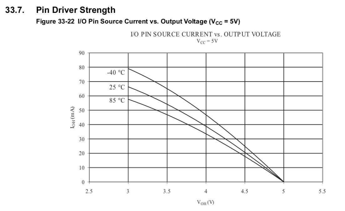
In the case of driving a resistive load connected to ground instead of to +5V, the calculations are similar. The specification says that sourcing 20mA (the minus sign means "leaving the pin") you can expect 4.2V on the pin, from which you can calculate the minimum resistance of about 210 Ohms. And page 443 of that specification has the appropriate graph if you'd like to do it that way:

enter image description here

\$\endgroup\$
14
  • \$\begingroup\$ So can I connect 100 ohm to arduino I/O or not? \$\endgroup\$
    – Kono
    Commented May 21, 2018 at 16:20
  • \$\begingroup\$ But you do like this: 5V/100 ohm = 50 mA. But due to low resistance, the voltage accross the resistance will be much lower (because the loadline is very steep, VDS wil increase so V over resistance will decrease). If the voltage is 2V, 2V/100 = 20mA so its not exceeding limit. \$\endgroup\$
    – Kono
    Commented May 21, 2018 at 16:26
  • \$\begingroup\$ That was an example. Because the loadline is steeper. The VDS wil increase over the transistor, and the V over resistor will decrease. As an example 5V lowers to 2V. (It could also be 4 or 3). \$\endgroup\$
    – Kono
    Commented May 21, 2018 at 17:05
  • \$\begingroup\$ In that case, the limit is not exceeded. And its fine to use 100 ohm. \$\endgroup\$
    – Kono
    Commented May 21, 2018 at 17:06
  • \$\begingroup\$ But that does not explain anything. The point is 5V will decrease because of low R. We dont know how much it will decrease because we dont know the characteristic of the transistors \$\endgroup\$
    – Kono
    Commented May 21, 2018 at 17:10
2
\$\begingroup\$

First, a little of background. There is a frequent misunderstanding what "GPIO maximum current" is. A digital GPIO pin of a microprocessor is not meant to supply current, it is designed to supply logical voltages. Therefore the outputs are usually specified and tested at some load conditions that provide certain voltage levels.

For Arduio (I assume ATmega2560 here) the OUTPUT VOLTAGES are defined as VOL at 20 mA load (when Vcc=5 V) and 10 mA load (when Vcc=3.3 V)

enter image description here

The output stage of silicon driver inside IC is complicated, and may contain many differently-sized transistors connected in a parallel push-pull manner, so a single I-V characteistics may not apply. Instead, we can figure out "effective impedance" of the port: If a port can bring a 20 mA load down to 0.9 V, it means the effective impedance (Rds(on) of the bottom NMOS) is about 0.9/0.02 = 45 Ohms.

Therefore, if you have a pull of 100 Ohms to +5V rail, the current through the pin might be 5/(100+45) = 34 mA. The Vout will be about 1.55 V at this pin.

This would be the first-order approximation fro worst-case silicon and temperature, since the Rds(on) will likely depend on Vsd voltage as well, but should be good as a ballpark number.

So yes, when you connect a 100 pull-up load to a ATMega2560 pin driven LOW, the pin will make 34 mA of current and have only 1.55V (at Vcc=5V), not 0.9 V logic level. Maybe a little lower, typically. However, the transistor will have to dissipate about 53 mW, which will cause spot overheating and possible damage to IC. Now it is up to you to decide if you want to drive 100-Ohms loads with naked Arduino pins.

EDIT: P.444 load curves in datasheet for ATmega128A indicates that electrically the pin can be loaded up to 80-90 mA. Apparently the 20 mA recommended current limit is for continuous load. But if your pin is operated in short pulses, and the average current doesn't exceed 20 mA (I guess it is due thermal limitation), the use of 100 Ohm pull-up can be justified.

\$\endgroup\$
2
  • \$\begingroup\$ I also wonder, IOL = 20mA, and VOL= 0,9 in TABLE. But when I check that graph VOL is about 0.3-0.5 when IOL is 20mA. Do you know why this is different? \$\endgroup\$
    – Kono
    Commented May 21, 2018 at 19:09
  • 1
    \$\begingroup\$ @Berkay, the difference is that DC specs table shows "worst case", while the I-V chart shows "typical case". Typical case is omitted in the table. \$\endgroup\$ Commented May 21, 2018 at 20:42

Your Answer

By clicking “Post Your Answer”, you agree to our terms of service and acknowledge you have read our privacy policy.

Not the answer you're looking for? Browse other questions tagged or ask your own question.