3
\$\begingroup\$

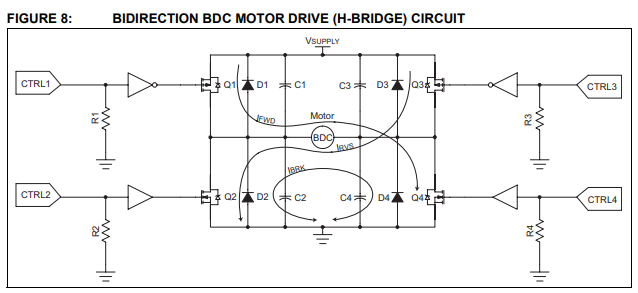
I always thought that if you want to reduce arcing in a motor commutator, you should put some capacitance across the motor terminals. But recently, while reading application note AN905 from Microchip, I saw this:

Motor drive circuit

Here, capacitors are placed across mosfets. Microchip says that the purpose of these capacitors is the same: to reduce the RF radiation that is produced by the arching of the commutators. So what's the difference between one capacitor in parallel with a motor and four capacitors like on the picture above?

\$\endgroup\$

3 Answers 3

4
\$\begingroup\$

Fundamental in the design of a H bridge that drives a dc motor is a bulk storage capacitor across the H bridge supply. This capacitor “soaks” up the leftover energy in the motor that will force itself onto the power rail. Therefore that capacitance (implied by your circuit) acts to somewhat stabilise the voltage supply and, in many cases it can recover braking energy.

So, the four capacitors in your circuit can be regarded as equivalent to a main bulk supply capacitor and a local arc suppression. There are many ways to skin a cat of course.

Personally I don’t like the four capacitor approach because the mosfets have a hard enough time with their own parasitic capacitance. My preference is a good solid bulk capacitor across the rails and an RC snubber across the motor but, like I said, there are many ways....

\$\endgroup\$
1
  • \$\begingroup\$ So this is an attempt to have it both ways. The energy reservoir and the snubber. Well, that's what I thought. Thanks! \$\endgroup\$
    – Dmitry
    Commented May 25, 2018 at 6:21
3
\$\begingroup\$

It depends . This is not a simple yes/no answer.

It is better for source EME or EME but maybe not load brush commutated temp rise to absorb arc energy if a brushed motor under full starting current (x10).

The schematic trace and cable impedance/ inductance is not shown so loop current transient flux and EME is not known. Thus in 2D simulations it may show where current pulse rises on conduction and current decay during dead time.

But how much interference is generated?

Simulations may also show but CM inbalance and direction of arc current during commutation and ripple current ^2 *ESR =Pc of Cap and thus temp rise and drop of MTBF of 50% approx per 10’C rise.

But it won’t do like COMSOL and graphically show crosstalk of mutual induction from interference to high impedance signals. (Advanced 3D EM physics)

For extreme cases RC//C can absorb more energy and filter EME noise better and possibly affect motor contact temp rise good or bad depending on snubbing or cap shunting making it worse.

Cables are the biggest problem or antenna source of common mode EMI or EME as some prefer to call it. But motor contact degradation from arc energy dissipation is also a key design factor and cap ripple current rating margin.

But if you don’t care about EME , the motor may reduce arcing during V=LdI/dt turn off duration but increase current during V/ESR=CdV/dt for a shorter duration but possibly higher current unless RC// smaller C with CM choke on motor cable. So both methods may be considered depending on layout .

Diodes also add some capacitance in addition to Coss.

The other concern is which diode has lower ESR ? Externals or internals to MOSFETS, If C of diode increases as ESR drops with rising Pd rating , you already have some deadtime load capacitance and current direction from the diodes is the same as previous conducting FET so the diodes need to be close to switch RdsOn for steady voltage from current FET switch during deadtime.

Thus if done right , keeping the Commutation current to the motor from the switches to diodes carrying the current will be decayed by the lumped capacitance across the switches more effectively than across the motor, because the cable is the noise antenna. This also demands that the driver to gate and motor ratio of RdsOn is low to drive the low ESR diode capacitance and EMI shunt Cap <=0.1uF according to DCR of motor current limit from winding resistance. Typically the ratio >20 or < 5%loss with ...
ratio =Motor DCR/ RdsOn of drain and
=. gate driver RdsOn / drain RdsOn for rough Rules of thumb 20 is minimum not 1000 while some are 100:1

\$\endgroup\$
2
  • \$\begingroup\$ Good answer about solving EMI problems. Thanks! But Andy was first and his answer was a little more specific. \$\endgroup\$
    – Dmitry
    Commented May 25, 2018 at 6:47
  • \$\begingroup\$ Look at variable RPM and conjugate match the snubber to the energy stored in the armature. \$\endgroup\$
    – D.A.S.
    Commented May 25, 2018 at 18:15
1
\$\begingroup\$

To filter out motor brush arcing an MOV of 20mm to 40mm in size and rated for 150% of the power supply will work fine.

This can be in addition to an RC snubber, such as 10 ohm in series with 100 nF. A snubber helps reduce noise at all times, while an MOV absorbs transients that have high-voltage peaks.

A capacitor can be placed directly across the motor contacts but is limited to filter just random RF noise and should not be over 1 nF.

A combination of these steps should quiet things down. Note that you cannot make brush arcing zero, but a 90% - 99% reduction would be very good.

The capacitors and diodes shown in the image are there to protect the MOSFETs, not the motor. Ideally C1 >> C4 should not be over 10 nF, or they begin to act like a capacitive load to the MOSFETs.

\$\endgroup\$
0

Your Answer

By clicking “Post Your Answer”, you agree to our terms of service and acknowledge you have read our privacy policy.

Not the answer you're looking for? Browse other questions tagged or ask your own question.