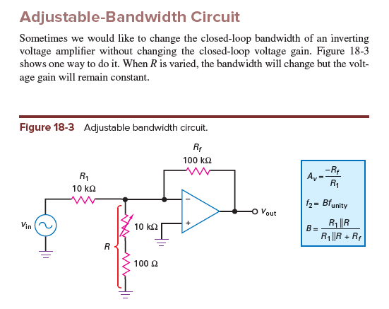
The shown circuit modification with a resistor R between the opamp input terminals is a very popular method for improving the stability margin of the closed lopp gain (input compensation).
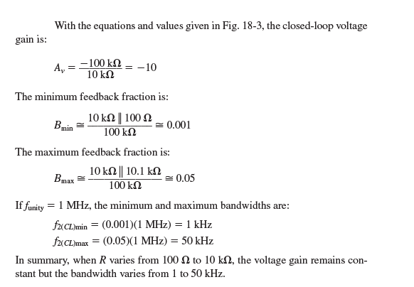
For ideal opamps (very large open-loop gain) the resistor R has no influence on the closed-loop gain but it lowers the LOOP GAIN (and, hence, the bandwidth of the closed-loop gain).
As a result, the stability margin is improved and we are allowed to use even opamps which are NOT unity-gain compensated for applications requiring closed-loop gain values as low as unity.
Intuitive explanation (for uneffected closed-loop gain):
Assuming that the open-oop gain Aol is infinity, the closed loop gain is Acl=-Hf/Hr with
Forward factor Hf=Vn/Vin for Vout=0 (Vn: Voltage at the "-"opamp terminal) and
Feedback factor (return) Hr=Vn/Vout for Vin=0.
It is easy to show that the additional resistor R lowers both factors in the same way so that the value of "R" cancels out in the ratio Hf/Hr.
Calculation:
Forward factor: Hf=(Rf||R)/[(Rf||R) + R1]
Feedback factor: Hr=(R1||R)/[(R1||R) + Rf]
After evaluation (and some mathematical manipulations) of the ratio Acl=-Hf/Hr we arrive at Acl=-Rf/R1 (R cancels out).
However, the loop gain (which is essential for stability properties) can be made as low as necessary by varying R:
Loop gain LG=-Hr*Aol (Aol: Open-loop gain of the opamp)


