0
\$\begingroup\$

I tried to make a PWM AC dimmer circuit which found in instructables.com as below: AC PWM dimmer by diy_bloke
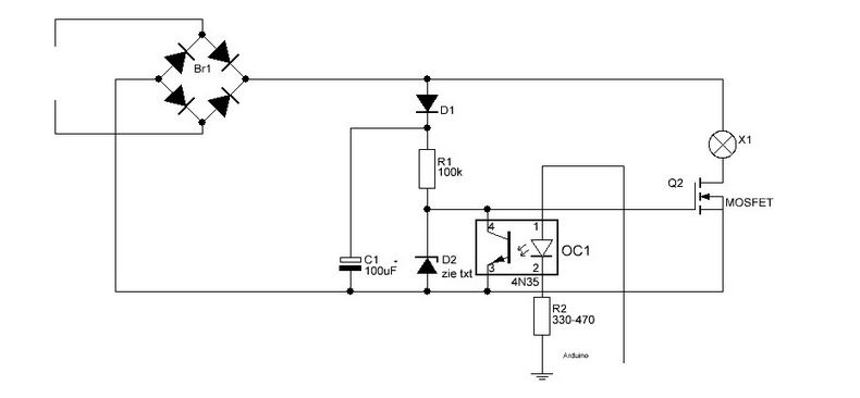
but the 100k 1W resistor got hot. Could using a pull up (or maybe pull down) resistor for optocoupler solve the problem?

\$\endgroup\$
15
  • 2
    \$\begingroup\$ How hot? How did you measure it? Warming up is part of a resistor's life. It would be good to give values of the other components used or to link the instructable. \$\endgroup\$
    – user133493
    Commented May 29, 2018 at 6:50
  • 1
    \$\begingroup\$ You were touching the circuit during operation? This circuit is powered from the line, right? Please give more information about what BR1 is connected to. If you're disconnecting the circuit before touching the part, I also hope you understand the danger from C1. \$\endgroup\$
    – user133493
    Commented May 29, 2018 at 7:01
  • 1
    \$\begingroup\$ I repeat, are you touching R1 while the circuit is live, or while C1 is charged? If this circuit is connected directly to the mains then it is rubbish. There isn't even a fuse. If you expect 330V across R1 then what is V^2 / R? \$\endgroup\$
    – user133493
    Commented May 29, 2018 at 7:13
  • 1
    \$\begingroup\$ At 3mA you are basically at the maximum dissipation capacity of the resistor. Awful. You basically made yourself mini space heater, not dimmer. \$\endgroup\$
    – Maple
    Commented May 29, 2018 at 7:23
  • 1
    \$\begingroup\$ Your resistor will be dissipating 1W. That means as a 1W resistor, it will get very hot. Depending on how the resistor is rated, perhaps 200C. It's designed to. Some reference temperatures - 40C feels warm to hot, 60C can touch, but can't hold finger on, 80C max for radiators can touch briefly without harm, 100C boiling water temperature causes harm to touch, 200C rated running temperature of some high power resistors. \$\endgroup\$
    – Neil_UK
    Commented May 29, 2018 at 7:25

2 Answers 2

1
\$\begingroup\$

That's quite a large electrolytic capacitor.. it will take some time to discharge through R1 to a safe voltage. 10uF would work as well and would be smaller, safer.

Nominal power dissipation is about 1W regardless of whether the opto is on or off.

If you want to stay with this, use a physically larger resistor rated at a few watts, and it won't get as hot (but of course it will be dissipating the same amount of power). Preferably a MOF type that is flameproof and rated for mains voltage.

enter image description here

\$\endgroup\$
3
  • \$\begingroup\$ Thanks a lot. Maybe the better option for this type of operation is MOF type but it is a bit unavailable in my place. \$\endgroup\$
    – ETeddy
    Commented May 29, 2018 at 16:59
  • \$\begingroup\$ Is it necessary to put a resistor in series with the gate of mosfet (to make a kind of RC circuit)? If answer is yes, how should it be calculated? \$\endgroup\$
    – ETeddy
    Commented May 29, 2018 at 17:03
  • \$\begingroup\$ No, you would really like it to switch as quickly as possible (within reason, but that optoisolator is very slow and the 100K resistor will charge the gate very slowly compared to what is possible with amperes available). \$\endgroup\$ Commented May 29, 2018 at 17:59
1
\$\begingroup\$

Looking at the schematic from instructables, there are several things wrong with it. Always take care when building things from Internet commentaries, because they have a tendency to make shortcuts.

d1 doesn't have surge protection from c1. c1 is grossly oversized. a 200 ohm resistor in series after d1 with a 4.7uf-22uf cap (adjust for flicker) instead of 100 uf cap. d2 looks like to me its getting tortured by having its source voltage pulled down by the opto at every pwm interval. btw, this zener is not needed, and a simple 6.8K resistor in its place when using the correct power mosfet (according to the commentary reading).

But what is the real current demand in the gate circuit supposed to be?

Here is a schematic of how the zener diode should have been implemented. In the schematic below, I added a 220 ohm resistor, and added a resistor to form a two pole voltage divider on the 100V tap, I stuck in a 100V zener, and now at the 15V tap we can provide this required voltage that you stated and the loading effects of the 15V wouldn't load down the zener. I don't know what current you need, but this schematic is more realistic than what was produced in that commentary.enter image description here
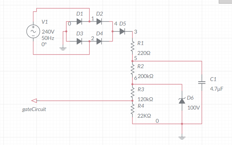
A little bit more info is needed: What device are you using as a mosfet. You should select a good power mosfet that has gate protection, most power mosfets have an anti inductive snubbing network built in.

\$\endgroup\$
4
  • \$\begingroup\$ I'll post a schematic \$\endgroup\$
    – drtechno
    Commented May 29, 2018 at 18:04
  • \$\begingroup\$ Thank you for your answer. Some parts of your answer I didnt understand clearly: 1- The voltage on C1 fluctuate from (near) 0 to (near) 330V so without a zener diode how can regulate the gate voltage of mosfet between 10 to 20V? 2- How can I calculate the capacity of C1 to have the smoothest DC voltage possible (the least ripple)? because the flicker tests require so much trial & error. \$\endgroup\$
    – ETeddy
    Commented May 29, 2018 at 18:12
  • \$\begingroup\$ The line regulation shouldn't fluctuate alot, but here is a schematic of what the gate circuit should look like with the proper anti surge, and zener diode connected properly in the circuit. \$\endgroup\$
    – drtechno
    Commented May 29, 2018 at 22:26
  • \$\begingroup\$ Thanks for the schematic. where should I place the load (lamp) in your circuit? I want to use this circuit to dim a 40W incandescent lamp by arduino pwm. I have two choices: first one is IRF730 mosfet and second is IRG4PC50W IGBT. \$\endgroup\$
    – ETeddy
    Commented May 30, 2018 at 2:32

Your Answer

By clicking “Post Your Answer”, you agree to our terms of service and acknowledge you have read our privacy policy.

Not the answer you're looking for? Browse other questions tagged or ask your own question.