A lumped element delay line is mimicing real life and real life is a transmission line (t-line). Examples are (but not limited to): -
- Coaxial cable
- Twisted pair
- A waveguide
- A PCB track and ground plane
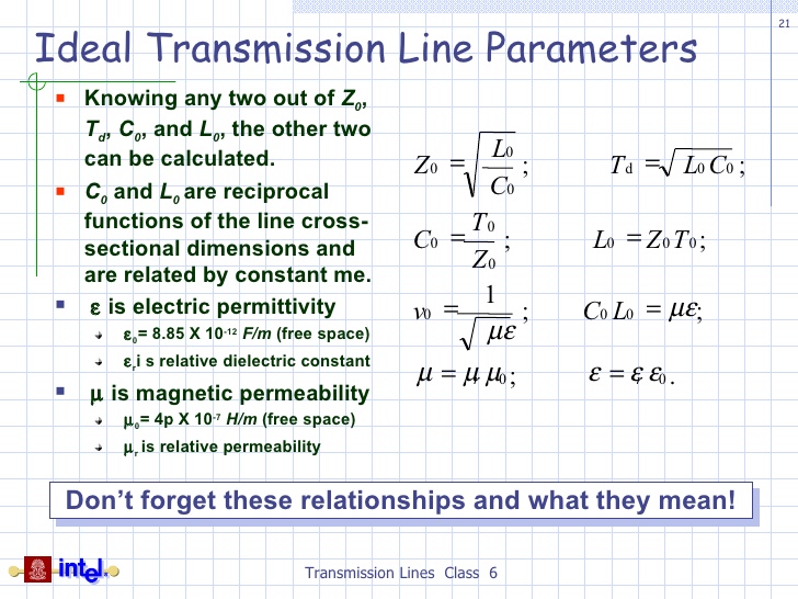
So, in real life a t-line has the following relationships: -

Picture part of this slide show.
All the above can be reasonably easily proven using transmission-line theory and the telegrapher's equations.
The expression was provided by the book I'm reading, but it did not
include how the time constant was derived
The expression in the book is based entirely on the distributed inductance and capacitance of a real t-line and so it is accurate, but only to a certain degree. As frequency rises (or rise/fall times shorten) the lumped-element model becomes less realistic.
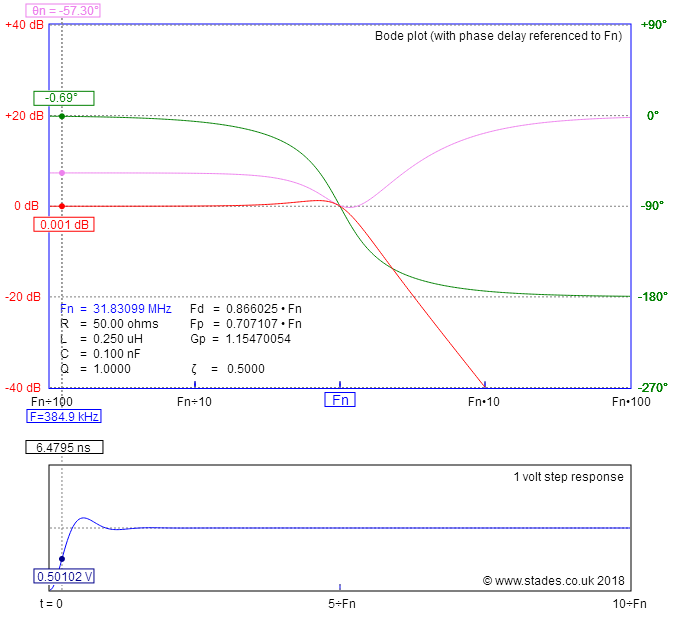
For example if I made a single element LC and chose the ratio of L to C to be 2500, the characteristic impedance would be \$\sqrt{2500}\$ = 50 ohm and so I feed the circuit from a 50 ohm source: -

I can choose R = 50, L = 250 nH and C = 100 pF. I've chosen L and C to be these values because they are broadly what a 1 metre length of 50 ohm coax will be. I get this result: -

Tool source.
In the lower part of the image is the step response and I've set the cursor to be about 50% of the 1 volt step applied. The time to reach this point is about 6.5 ns. If I did the calculation: -
$$t_D = \sqrt{LC}$$
I get a value of 5 ns. Not a million miles off and hopefully you can see that lumped element lines are not quite what the theory states because they are trying to mimic a real t-line.


