I’m trying to receive CAN frames on a STM32F412G-DISCOVERY with a SN65HVD233 transceiver, transmitted from a USB2CAN device. Both are connected on a bus of about 15 cm long with two 120 Ω resistors on each end.
I connected an oscilloscope to read the RX and TX pins on the STM32 board before they are transformed by the transceiver. When I configure the CAN controller in silent mode and send a CAN frame from the USB2CAN using:
$ cansend can0 '144#25'
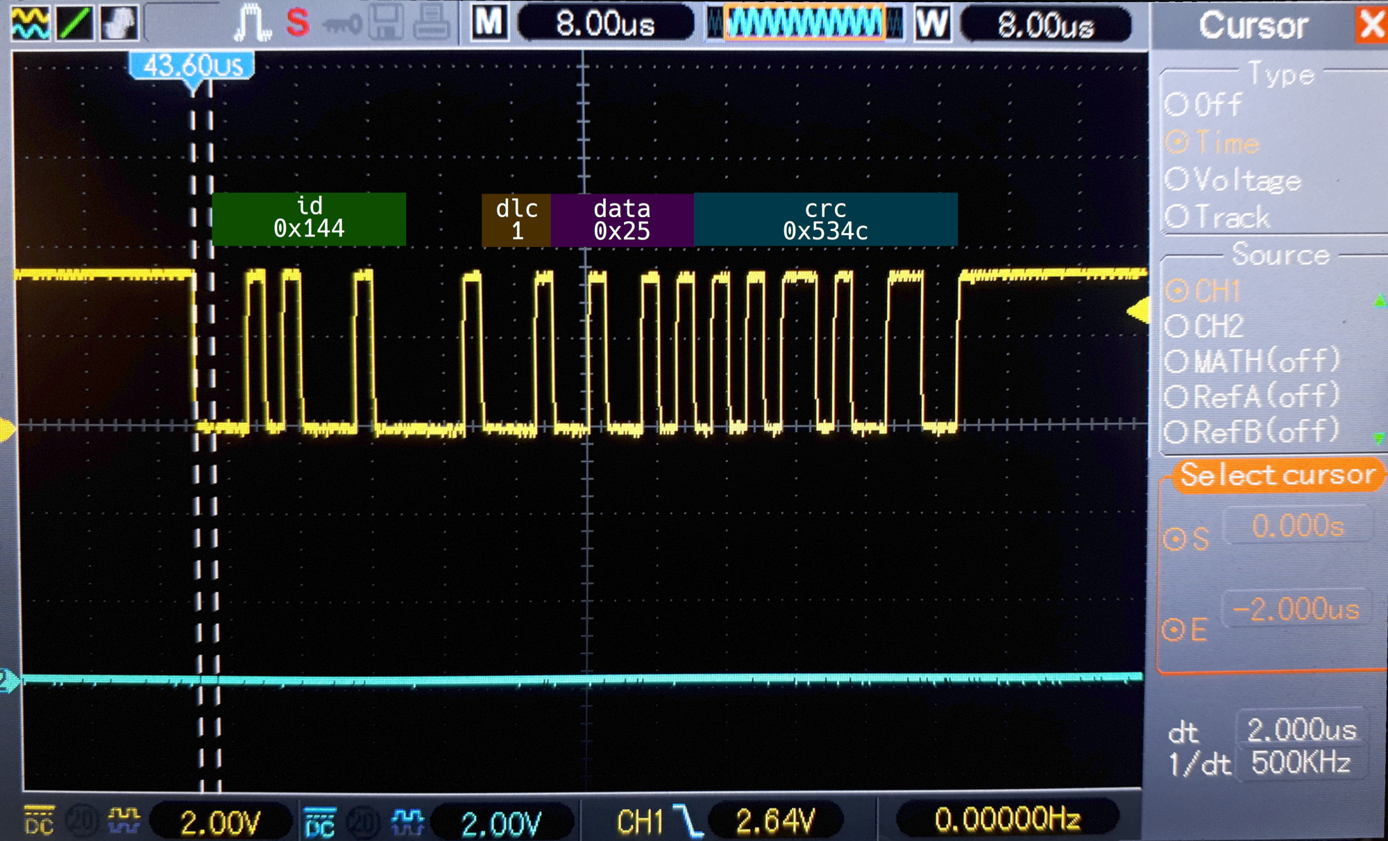
I see on the oscilloscope on the RX pin the full frame (yellow is the board’s RX, blue its TX):
NB: the cursor indicate the time interval of one bit (2 µs, bitrate is 500 kb/s).
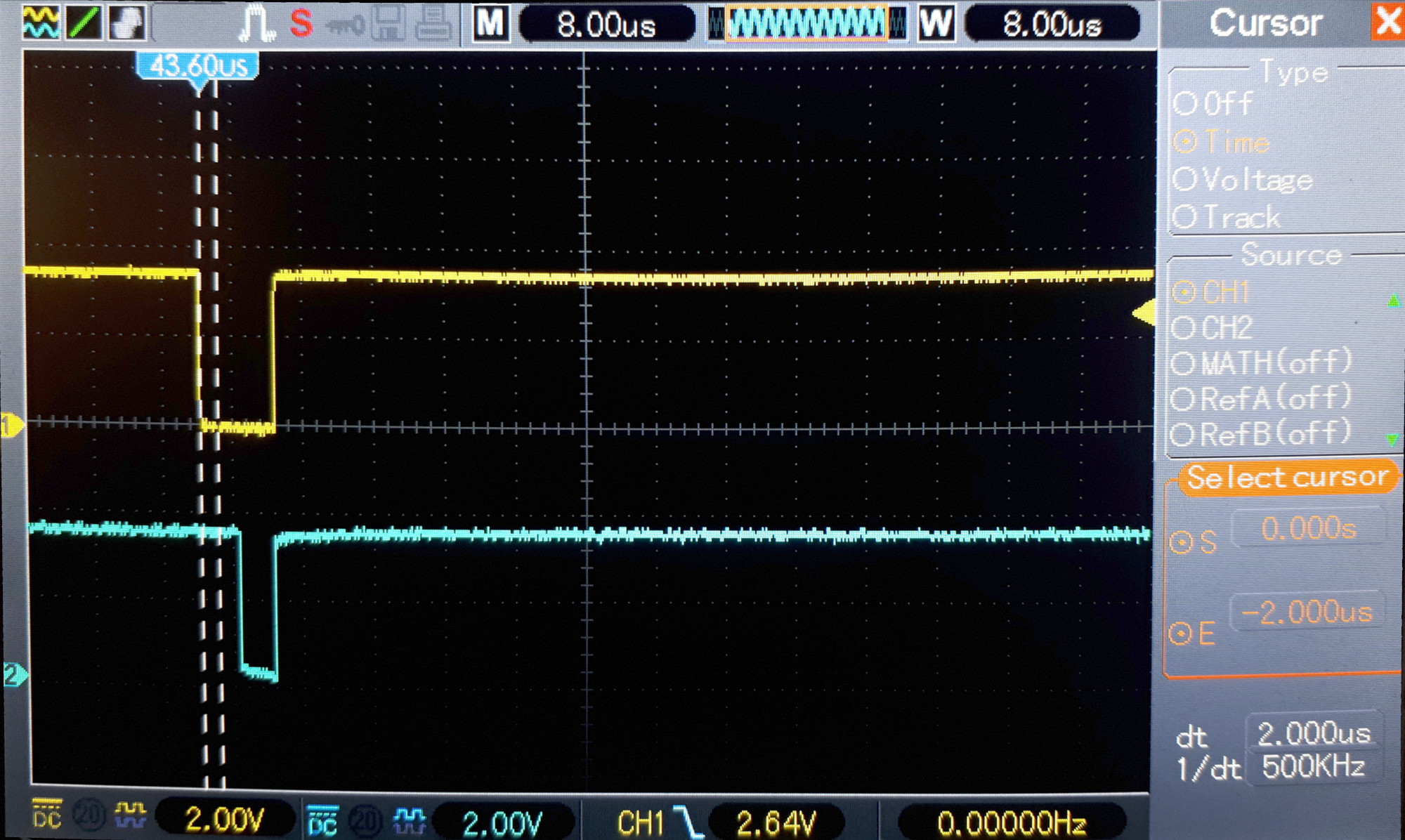
(The HAL_CAN_Receive call still timeout, but that is another problem.) But when I put the controller in normal mode, here is what I measure:
And here is the code:
hcan1.pTxMsg = &g_out_msg;
hcan1.pRxMsg = &g_in_msg;
hcan1.Instance = CAN1;
hcan1.Init.Prescaler = 12;
hcan1.Init.Mode = CAN_MODE_NORMAL;
hcan1.Init.SJW = CAN_SJW_1TQ;
hcan1.Init.BS1 = CAN_BS1_1TQ;
hcan1.Init.BS2 = CAN_BS2_1TQ;
hcan1.Init.TTCM = DISABLE;
hcan1.Init.ABOM = DISABLE;
hcan1.Init.AWUM = DISABLE;
hcan1.Init.NART = DISABLE;
hcan1.Init.RFLM = DISABLE;
hcan1.Init.TXFP = DISABLE;

if (HAL_CAN_Init(&hcan1) != HAL_OK)
    fatal_error("failed to init HAL CAN.");

CAN_FilterConfTypeDef sFilterConfig;
sFilterConfig.FilterNumber         = 0;
sFilterConfig.FilterMode           = CAN_FILTERMODE_IDMASK;
sFilterConfig.FilterScale          = CAN_FILTERSCALE_32BIT;
sFilterConfig.FilterIdHigh         = 0x0000;
sFilterConfig.FilterIdLow          = 0x0000;
sFilterConfig.FilterMaskIdHigh     = 0x0000;
sFilterConfig.FilterMaskIdLow      = 0x0000;
sFilterConfig.FilterFIFOAssignment = 0;
sFilterConfig.FilterActivation     = ENABLE;
sFilterConfig.BankNumber           = 14;
if (HAL_CAN_ConfigFilter(&hcan1, &sFilterConfig) != HAL_OK)
    fatal_error("failed to setup CAN filter.");

HAL_StatusTypeDef can_status;
if ((can_status = HAL_CAN_Receive(&hcan1, CAN_FIFO0, 20000)) != HAL_OK)
    fatal_error("failed to receive frame: %d", can_status);
It seems that the emitter (USB2CAN) tried to write a recessive (1) for the 2nd bit of the ID while the receiver (STM32) sent a dominant (0): the emitter detected that collision and stopped emitting.
Why did the STM32 CAN controller sent that dominant bit which stopped the communication?


