1
\$\begingroup\$

I'm trying to build a boost converter with the following specifications.

  • Switching Frequency: 100 kHz
  • Maximum Input Voltage: 14 V Nominal
  • Input Voltage: 12 V
  • Cutoff Input voltage: 10.5 V
  • Power rating: 1000 VA
  • Transformer type: Push-pull transformer for boost converter
  • Number of primary windings: 1 - Center tapped (10 V - 14 V)
  • Number of secondary windings : 1 (350 V)
  • Number of auxiliary windings : 1 (15 V, 2 A)

The thing I'm confused about is how to select the right core for this design. I know that this design would need a EE core but rest selection parameters are what I'm really confused about. Such as selection of operating flux (Bmax) (is it based on power, current or it's independent), core material, interpreting Al value given in the datasheet, selection of core with respect to power rating of the application. I read articles from "tahmidblog" here about transformer design. There he explained rest of the parameters calculations excellently but choosing a core particularly is what I'm not understanding clearly. Please help me understanding it, for example how to select a core material depending upon power?

\$\endgroup\$
5
  • \$\begingroup\$ "Boost converter using push-pull topology" does not make much sense. You want to make a push-pull forward converter with higher secondary output voltage than input? \$\endgroup\$
    – winny
    Commented Jun 12, 2018 at 10:26
  • 1
    \$\begingroup\$ Go find the ferroxcube handbook (a big reference) and look up the various powers you can use with ferrites. There are graphs and select you core material from that starting point. Then decide what primary inductance you need to have to avoid saturation of the core. \$\endgroup\$
    – Andy aka
    Commented Jun 12, 2018 at 10:51
  • \$\begingroup\$ @winny yes. I thought the topology is named as push-pull so I mentioned it that way. The output of the converter would be higher than the input. \$\endgroup\$
    – Sai Prasad
    Commented Jun 12, 2018 at 14:30
  • \$\begingroup\$ Please look it up. Push-pull is a resonable choice for your inside it voltage level. \$\endgroup\$
    – winny
    Commented Jun 12, 2018 at 14:33
  • \$\begingroup\$ You could look at a 3F3 E65 Planer \$\endgroup\$
    – Autistic
    Commented Feb 21, 2020 at 8:22

2 Answers 2

2
\$\begingroup\$

Such as selection of operating flux (Bmax) (is it based on power, current or it's independent)

Bmax is based on the residual current that flows in the primary irrespective of load. So, it's not based on power-throughput but it is based on current (but not load-current).

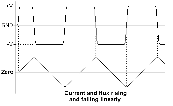
Imagine you stripped away the secondary and drove the primary winding. You have primary inductance and when you apply a voltage to that inductance, current rises linearly (hopefully). That rising current is determined by: -

$$\dfrac{di}{dt} = \dfrac{V}{L}$$

That rising current produces a rising flux.

Then when you activate the other transistor, an equal value of inductance is connected that linearly ramps down the flux to a negative value and the process repeats: -
enter image description here

The average level of flux is zero and it peaks at negative and positive values. That is what you ideally want. But a magnetic core isn't perfect and it does saturate and that starts to produce anomalies in the current so you try and keep these anomalies at bay but you do have to accept some saturation.

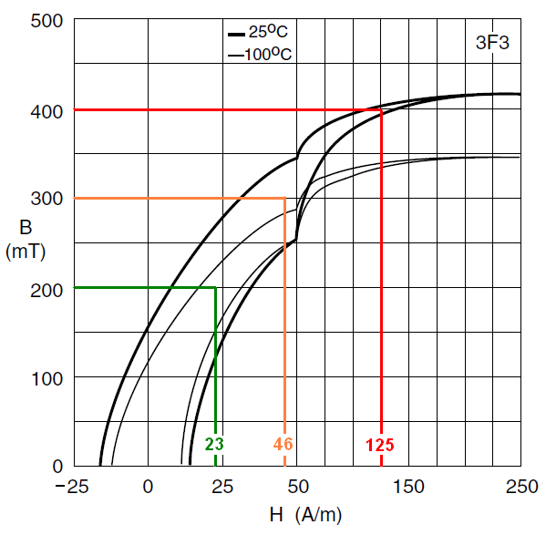
Take Ferroxcube 3F3 material (just as an example): -
enter image description here

Picture source.

The material hard saturates at about 400 mT (at 25 °C) and it will get hot if driven at this level (see red line in picture). As it warms the saturation level drops to about 340 mT (at 100 °C) and things just carry on getting hotter. This must be avoided.

So, instead of driving it at 400 mT consider driving it at 200 mT (green line). Now it is fairly temperature stable should temperature rise due to (say) copper loss. You can also say that maybe 300 mT is a good level but I initially tend to stick at 200 mT for this type of material.

Getting back to the root problem; the primary inductance is driven with a voltage and will produce a triangle wave of current (and flux) and, the peak of that current is the point at which flux is highest (and hence flux density is highest).

Note that in the BH diagram above, the H value is about 23 ampere turns per metre to deliver 200 mT.

And this is now getting towards solving the issue of how many turns are needed. If you chose a core type that has an effective length of 150 mm and an inductance factor (\$A_L\$) of 2000 nH/t and initially considered 18 uH to be an adequate inductance then you will need three turns because one turn gives 2 uH and inductance is proportional to turns squared hence 3 turns gives 18 uH.

With 18 uH and (say) 12 volts applied over half the switching period (dt), current (di) is 3.333 amps. That value is the peak current both positively and negatively. So the peak ampere-turns is 3.333 x 3 = 10 At.

To convert to H you divide ampere-turns by the length of the core so now H is 10/0.15 = 66.7 At/m and too big for the flux density limit of 200 mT. You need to change inductance to a higher value so maybe you go for 6 turns (an inductance of 72 uH).

I should say that I'm explaining a process rather than giving a solution that is suitable for the OP....

The peak current will be 0.8333 amps and the ampere-turns will be 5 At. The H field will be 5/0.15 = 33 At/m and will probably result in a peak flux density of about 240 mT and this will likely be OK.

So, in summary: -

  • You need a core size that has a significant effective length in order to keep the H field low
  • You need to choose a core material that is good for 100 kHz
  • You need to choose a primary inductance that doesn't take so much current in the no-load scenario that excessive saturation takes place.

interpreting Al value given in the datasheet

For one turn it tells you how much inductance you get and you multiply that by turns squared to give you total inductance.

how to select a core material depending upon power?

If you can fit 6 turns of thick copper wire (and don't underestimate how thick this needs to be to deliver nearly 100 amps of load current AKA 1000 VA from a 12 volt source) AND you can fit the secondary winding then this will work providing the copper losses are not so excessive to cause problems.

And, of course, with the split primary design you have, you'll need 6 + 6 primary turns because only one half is active at any time. I have done a similar design for about 200 watts and to keep efficiency as high as I could, I hard switched the primary as per your design but the centre tap I fed from a 95% efficient synchronous buck converter to do the regulation.

I'm not saying that this is the best route to go for you but I am saying that for my design this suited what I needed to achieve AND I ran at an operating frequency much higher than 100 kHz i.e. 600 kHz. Running higher than 100 kHz is probably what you'll need to do so maybe consider 250 kHz and choose a slightly more exotic ferrite material such as 3F3.

Choosing a core can be very difficult and a bit of try-this, try-that theoretically is par for the course.

\$\endgroup\$
1
  • \$\begingroup\$ Thank you very much @Andy aka . Your explanation gave me an idea of how things work internally. \$\endgroup\$
    – Sai Prasad
    Commented Jun 13, 2018 at 6:18
1
\$\begingroup\$

There are two ways to run coupled inductors in a power converter.
(a) without energy storage, as a transformer, often driven in push-pull.
(b) with energy storage, as a flyback, often referred to as a boost converter.

The (a) type requires a high permeability core, with no airgap. The (b) type requires either an airgap, or a low permeability core, to make best use of the energy storage in the core. Make sure you know which type you're building before you choose a permeability.

We usually limit the core flux due to thermal considerations. With ferrite at 'normal' frequencies in the mid to high 10s to low 100s of kHz range, these tend to bite before simple saturation. As the core power dissipation is due to a certain flux dependent energy loss once per cycle, a high frequency core will have to run at a lower peak flux density, which means less energy loss per cycle, than a low frequency one. Generally the ferrites with the lower energy loss per cycle are more expensive (surprised?)

\$\endgroup\$
2
  • \$\begingroup\$ Type (a) can certainly have an air gap in order to avoid saturation. Sure you will need more turns to "get back" the inductance but the overall flux density will be lower. \$\endgroup\$
    – Andy aka
    Commented Jun 12, 2018 at 13:57
  • \$\begingroup\$ @Andyaka Please don't restart this 'avoid saturation' stuff. It's true that at constant current, in two otherwise identical cores, one with, one without a gap, that the gapped one will run at a lower flux density. But that's putting the cart before the horse. A transformer is designed to run at the maximum flux possible, otherwise there's no point in using that expensive ferrite. Given the flux is fixed, we manipulate the effective permeability to maximise (for flybacks) or to minimise (for transformers) the energy storage. Adding a gap 'to avoid saturation' is what amateurs do. \$\endgroup\$
    – Neil_UK
    Commented Jun 12, 2018 at 14:28

Your Answer

By clicking “Post Your Answer”, you agree to our terms of service and acknowledge you have read our privacy policy.

Not the answer you're looking for? Browse other questions tagged or ask your own question.