3
\$\begingroup\$

First, let me say that I'm very new to electronics so this issue may just be down to me doing something wrong.

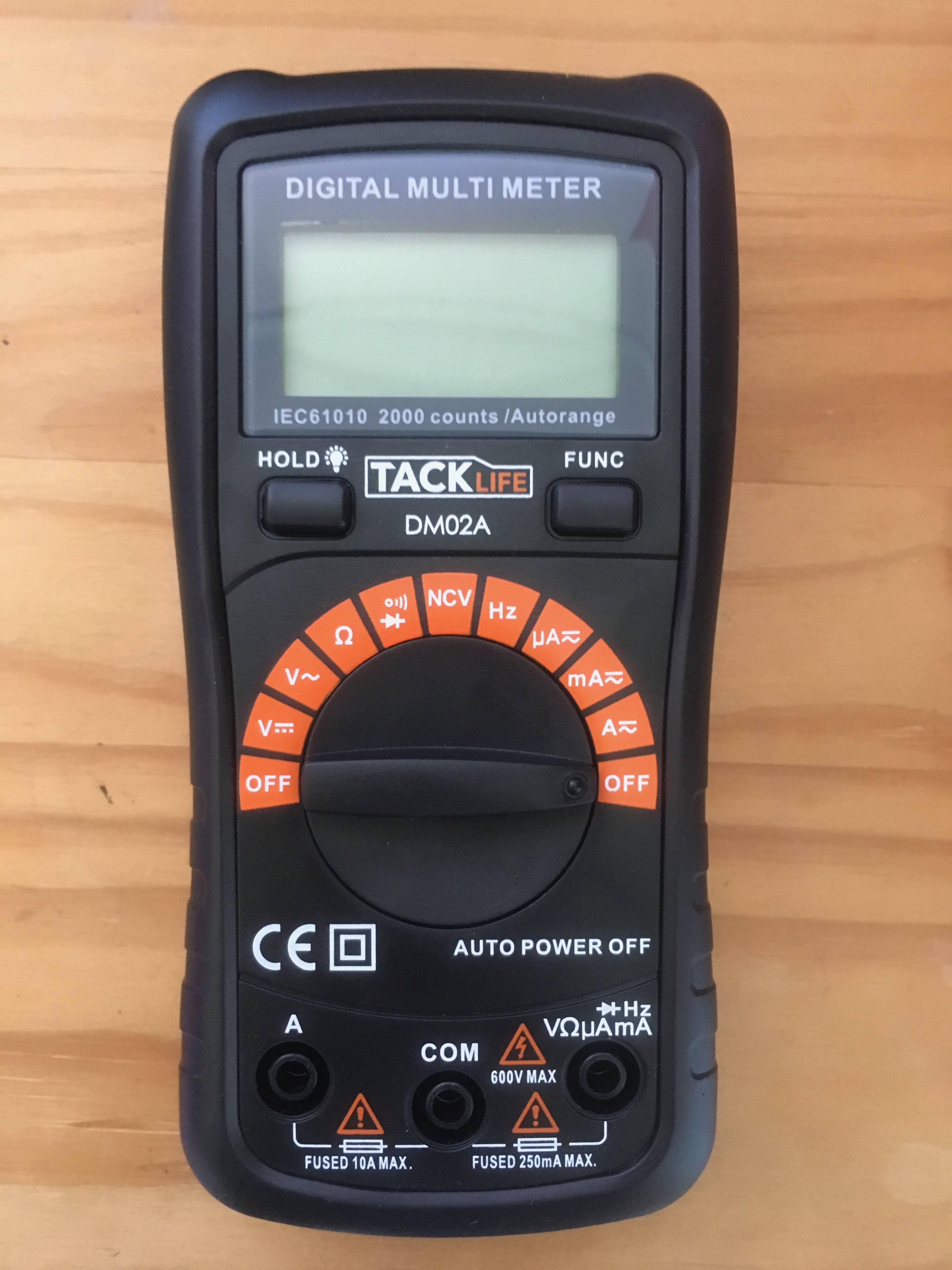
Here is my multimeter: enter image description here

It started when I was trying to test the gain of a PNP transistor. The expected values were 0.016mA for base and 3.1mA for collector. I kept getting 0.03mA for both. My multimeter has 1 terminal for A and another terminal for everything else, including mA (I was using the mA terminal). I assumed I was just doing something wrong but eventually decided to test the multimeter on a simple circuit.

I connected an LED, a 470 ohm resistor and the multimeter in series as a test. With no multimeter, the LED is on. Using the A terminal, the LED is on and has a value of 0.014A. Using the mA terminal, the LED is not on and the reading is 0.03mA.

So my question is: am I just messing this up somehow or is my multimeter broken?

The options I have considered are:

  1. The multimeter is working and I have just made a mistake somewhere.
  2. The current in the test circuit with the mA terminal is actually 0.03mA. The low current could be the reason the LED isn't turning on. But why would it work fine using the A terminal?
  3. The multimeter with the mA terminal is not forming a circuit for some reason. This would explain why the LED won't switch on. However, the multimeter reading does increase from 0 to 0.03mA once the battery is connected, which suggests some current is flowing.

All in all, I'm very confused. I only started this a few days ago so have no idea what I'm doing. I did test the current of the same test circuit yesterday (using the mA terminal) and I didn't notice it giving a really low value, but I wasn't really paying attention.

\$\endgroup\$
9
  • 4
    \$\begingroup\$ Check the fuse. The mA terminal is fused, so if you measure a current higher than it is rated for, the fuse will burn. \$\endgroup\$
    – Eugene Sh.
    Commented Jun 14, 2018 at 19:37
  • \$\begingroup\$ You need to edit your question to include a make, model and photo of your meter. Pictures are much better than words. If you can include a second photo of one of your test measurements we may help further. \$\endgroup\$
    – Transistor
    Commented Jun 14, 2018 at 19:39
  • 2
    \$\begingroup\$ You can always use the meter to measure the drop across a resistor and calculate the current with Ohms Law as I=V/R. Many times that is easier than putting the meter in line. \$\endgroup\$
    – crj11
    Commented Jun 14, 2018 at 19:44
  • 2
    \$\begingroup\$ Why don't you perform some simple control experiments? Take a AA battery, and a 150-Ohm resistor, nothing fancy, no LED nor transistor. And then just check if your readings are in line with Ohm's Law. \$\endgroup\$ Commented Jun 15, 2018 at 2:23
  • 1
    \$\begingroup\$ The make, model and photo of the meter is less relevant than a simple drawing on how you actually connect the wires. Maybe you don't know to connect current measurements in series, or something else. \$\endgroup\$
    – pipe
    Commented Jun 15, 2018 at 8:42

1 Answer 1

3
\$\begingroup\$

After testing the multimeter some more with help from the comments on my question I found out that the fuse was blown. Thank you everyone for your help.

\$\endgroup\$
1
  • 1
    \$\begingroup\$ A quick tip: you can use a diode/continuity test to check if your fuse tripped. It is THE most common problem with a faulty current reading. In a semester, my first year students uses roughly 30 to 40 fuses. Most often, they tried to measure a current in parallel. \$\endgroup\$ Commented Jun 15, 2018 at 12:50

Your Answer

By clicking “Post Your Answer”, you agree to our terms of service and acknowledge you have read our privacy policy.

Not the answer you're looking for? Browse other questions tagged or ask your own question.