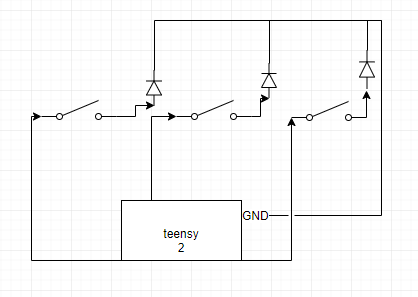
LEDs are non-linear devices when it comes to their forward voltage. They have a narrow range (by voltage) where they work optimally. Too little voltage and they don't conduct, too much and they fail.
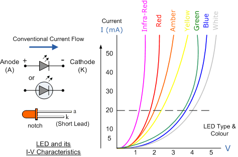
Credit: B. Gashiii
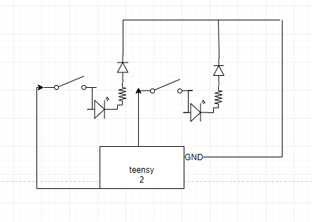
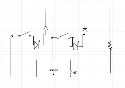
There are other questions which address the proper ways to connect and power LEDs; but simply put, you need constant current. The most straightforward way to connect LEDs is to use a current-limiting resistor with fixed voltage sources. You're on the right track with the inclusion of current-limiting resistors, but you have two different methods in your examples.
Let's simplify these by eliminating the switches for the moment and just examining the differences between having LEDs share a resistor versus having dedicated ones.
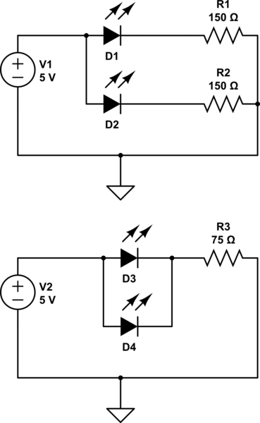
simulate this circuit – Schematic created using CircuitLab
In the top example, each LED has a resistor to limit current through it. In the lower example, the LEDs share a resistor to limit current through the two in parallel. (I've selected resistor values for LEDs having a Vf of 2V and a nominal current of 20 mA.)
I've eliminated switches, so these examples are for "all LEDs lit" situations, which you would achieve by pressing all switches simultaneously.
If you examine this question about LEDs in parallel, you'll discover that while it works in theory, it doesn't usually work well in practice. What happens is one LED has slightly different physical characteristics than others, and current is not shared equally. Over time this leads to various problems.
The other problem occurs at the introduction of switches. When you have a single resistor, how can its value be appropriate for a variable number of lit LEDs? The answer is that it can't, so you should have a resistor for each LED.
Up to this point, I've ignored two other aspects of your question: The microcontroller and the switching diodes. From the way you worded your question, I am assuming you want to read switch state with the microcontroller, but light the LEDs with the press of a switch.
An LED is also a diode (Light Emitting Diode). So you shouldn't need the additional diodes at all. They will introduce an additional small voltage drop (about 0.8 - 0.9V depending on temperature and current).
The pins on your microcontroller should either be configured as input pins, to read the switch state, or output pins to drive LEDs. These are conflicting situations, better discussed in this question. Depending on which Teensy you have, you may need to dedicate some pins as output to drive the LEDs and some pins as input to read the switch states. You might not have enough pins, so that leaves you having to either multiplex switches and/or LEDs or use a microcontroller with more I/O pins. There might be other options as well, but you should ask a new/separate question once you've narrowed it down a bit. Hope this helps.

