1
\$\begingroup\$

I have a problem with my mppt solar voltage regulator. I have a campervan with three 320 W solar panels (Voc 40.8 V, Vmpp 33.3 V) connected in series on the roof, and two 260 Ah, 12 V AGM batteries connected in series to get a 24 V system. I've set the correct absorption (28.5 V) and float (27.4 V) charge voltages (as per battery specs), and the MPPT regulator can handle up to 145 V Voc and has an MPPT range of 30-115 V, with up to 60 A charging current, so it should be able to handle the solar panels perfectly.

The problem is, when I move the van from a shadowed area to a well lit one, I get a two second voltage surge from the MPPT charger that goes over 30-31 V. This makes my inverter overvoltage protection trigger, cutting AC power during those two seconds. It's very annoying because when power comes back some appliances automatically turn on.

Is there anything I can do to force an upper limit on the regulator output voltage, without compromising efficiency?

\$\endgroup\$
4
  • 1
    \$\begingroup\$ Got battery and MPPT datasheet links? And age or condition of batteries? \$\endgroup\$
    – D.A.S.
    Commented Jun 21, 2018 at 14:27
  • \$\begingroup\$ Got inverter specs or datasheet? \$\endgroup\$
    – D.A.S.
    Commented Jun 21, 2018 at 14:45
  • \$\begingroup\$ Hi Tony, thanks for answering and sorry for the late reply. 260AH Battery specs, MPPT 3KVA Plus specs, at end of file (it's a combi unit, normally I do not use the integrated inverter because of it's high no-load consumption, just the charger and MPPT voltage regulator),Inverter PS350-24 specs \$\endgroup\$ Commented Jun 27, 2018 at 8:49
  • \$\begingroup\$ well i dont im not happy with the accepted answer, what did you find out op ? \$\endgroup\$ Commented Dec 6, 2019 at 19:14

2 Answers 2

0
\$\begingroup\$

Speculation

This may suggest a fault in either the MPPT circuit design or the batteries have weak cells from sulphation causing the O.V. condition with high ESR raising 2.23V cells in absorption to rise 2.5V collectively with 900W/30V=30A meaning the bat. pack has an ESR > 2.5V/31A=81 mOhm. If you have a CCA type battery tester or makeshift pulse charge or load test, you may be able to see which battery is at fault. If new, then the batteries may be poor quality or high ESR on wire connections which should not occur on 240Ah batteries.

Got battery specs?

I would expect new 240Ah AGM batteries to be <5 mOhm each and cables+connections to be same or less when fully charged and new. This rises with age and low SoC.

Got test results of battery connector ESR?

If 29V is OK for inverter then max battery + cable + contacts ESR must be < 17 mOhm approx. = 0.5V/ 30A rise.

Otherwise we need to examine the inverter protection features and drop the input voltage 2V at the expense of 60W max wasted power from limited voltage range of inverter.

\$\endgroup\$
4
  • \$\begingroup\$ I havent tested the batteries, but they appear to be working fine (sustained load makes for a congruous voltage drop). The inverter overvoltage limit is 31V. I think the problem lies in the MPPT circuit design, as when fully lit the panels output a voltage near to the 115V MPPT range top limit, and maybe that's why it's not behaving as it should. \$\endgroup\$ Commented Jun 27, 2018 at 8:56
  • \$\begingroup\$ Warning: MPPT Absolute Max: Voc=37.7 <40.8V from dark to bright sunlight may occur. Protection delays may result. Complain to supplier of system for bad choices. Low SoC batteries can also react this way to MPPT high current from poor MPPT fault recovery from O.V.P. protection (hiccup mode to exceeding input Voc range not to mention yet on inverter reaction. This is speculative , but I understand some designs may do this. \$\endgroup\$
    – D.A.S.
    Commented Jun 27, 2018 at 15:29
  • \$\begingroup\$ The design may not perform as expect if Voc input is exceeded. This can be corrected with your own OVP to meet 37V with a precision OVP sensing dummy load if so desire that reacts in <<1ms for low cost but needs custom design \$\endgroup\$
    – D.A.S.
    Commented Jun 27, 2018 at 15:36
  • \$\begingroup\$ If interested perform ESR vs Vbat test with a pulsed 10A step load test for V drop isolated from system and keep records \$\endgroup\$
    – D.A.S.
    Commented Jun 27, 2018 at 15:50
1
\$\begingroup\$

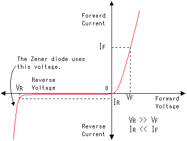
A simplistic solution is to mount a large amount of 30V zener diodes in parallel. They will swallow the over voltage and turn it into heat.

Google "DIODE ZENER 30V 5W" for 5Watt diodes. 10 of these would withstand 50 W continuous. There are larger ones, but they cost more. You will find them on ebay and the usual electronics distributors like mouser, farnell, digi-key among others.

This block would be connected across the poles of your charger, i.e. in parallel with your batteries. Be cautious though, as they have a sloping "on" characteristic, i.e. they may waste a little current at normal operation. So maybe "31V Zener" is better, if available. Also, more diodes in parallel make for "quicker high consumption" i.e. less voltage rise before the combined pack starts to draw current and load your MPPT. I found the descriptive image below by googling. (Note these weird diodes are used in reverse, hence the "reverse" voltage and current). Zener diode chacteristics

\$\endgroup\$

Your Answer

By clicking “Post Your Answer”, you agree to our terms of service and acknowledge you have read our privacy policy.

Not the answer you're looking for? Browse other questions tagged or ask your own question.