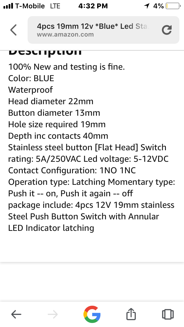
Attached is a screenshot of my button and the dimmer I found, it’s getting a 12V source. I figured using wiring the pwm dimmer like the one shown will work. Please let me know your suggestions on if the dimmer will work and how to wire it inline with the switch to dim the led light.
-
5\$\begingroup\$ Trim all the crap from your pictures already! \$\endgroup\$– Olin LathropCommented Jun 27, 2018 at 11:22
-
\$\begingroup\$ Not sure why you would downvote this, it is a great question on the design and application of electronics knowledge for everyday life. \$\endgroup\$– Joe SCommented Jun 27, 2018 at 11:31
-
6\$\begingroup\$ @Joe: I imagine the downvotes are for dumping overly large untrimmed pictures on us. What's the point of showing us the Amazon search bar, the fact that the phone is running out of battery, the icons on the bottom of the page, etc? That's just laziness and gross disrespect of the volunteers here. Then there is a bunch of text that is excessively large, making it actually difficult to read. \$\endgroup\$– Olin LathropCommented Jun 27, 2018 at 11:37
-
\$\begingroup\$ It's not an electrical engineering solution, but I would just use a piece of translucent tape. Cheap masking tape would allow the light to shine through dimly. \$\endgroup\$– davidmneedhamCommented Jun 27, 2018 at 13:39
2 Answers
This seems to be the only relevant part of the pictures you posted:
It seems to show that the LED connections are independent of the switch connections.
To decrease LED brightness, you decrease the current thru the LED. Since you didn't actually post or link to any real specs for this switch, we don't know whether there is a bare LED inside, what its forward voltage is, or whether there is a resistor in series.
In any case, adding a resistor in series externally should reduce the brightness. Without specs we'd be guessing at the value. Try in the range of a few 10s of Ohms to a few 100 Ohms and stick with what you liked best.
It looks like the terminals labelled + and - go to the internal LED. The wiring diagram shows you to connect the NO terminal to the +. This connects the switched power to the LED, so the LED only lights when the switch is ON. I presume that the internal LED has a current limit resistor in series with it, otherwise it would instantly fail.
To dim the LED you need to reduce the amount of current flowing through it by introducing more series resistance. You can do this by connecting a resistor between the NO terminal and the + terminal rather than connecting them directly as shown in the wiring diagram. Since I don't know the spec of the LED you will have to try different values of resistor until you get your preferred brightness. Start with 1k. If that is still too bright go higher in resistance. If 1k is too dim, go lower in resistance.
-
\$\begingroup\$ Also the load is shown connected to +, so that would have to change to NO. \$\endgroup\$ Commented Jun 27, 2018 at 15:02